Konica Minolta CM-26 CM-25
Installing the Konica CM-25 & CM-26 driver
The Konica Minolta CM-25/26 driver is only available in Windows version.
Driver download for KM CM-25/26
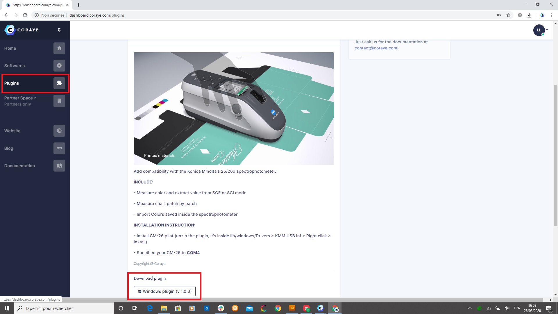
The drivers are included in the Coraye plugin of the CM-26 which can be downloaded from the dashboard: https://dashboard.coraye.com/plugins
Once the plugin is downloaded, unzip it.
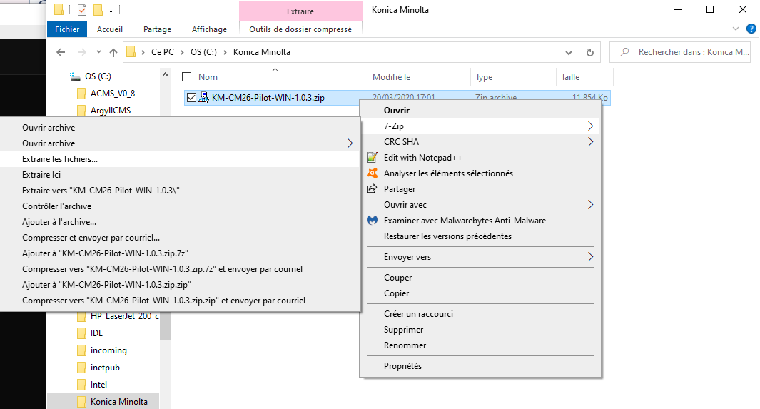
The driver is located in the folder: C: \ .... \ KM-CM26-Pilot-WIN-1.0.3 \ lib \ windows
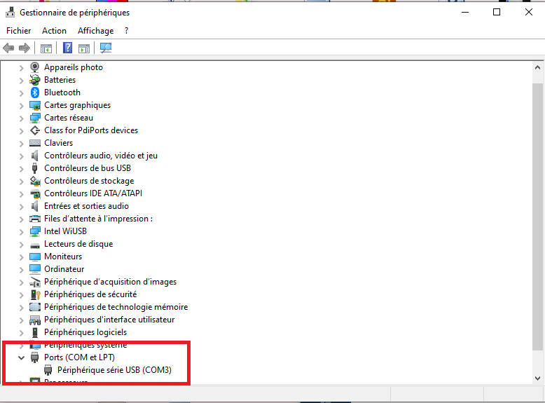
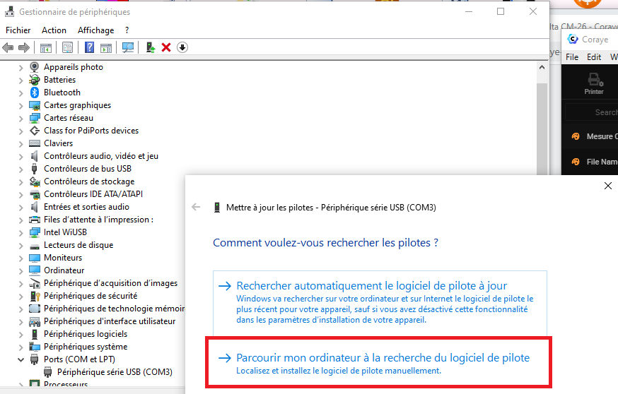
When you connect the KM CM25 / 26 for the first time, it will appear as " USB Serial Device " in Windows Device Manager.
This means that the CM25 / 26 driver has never been installed.
To install the driver, right click on " USB serial device " then select " Update driver "
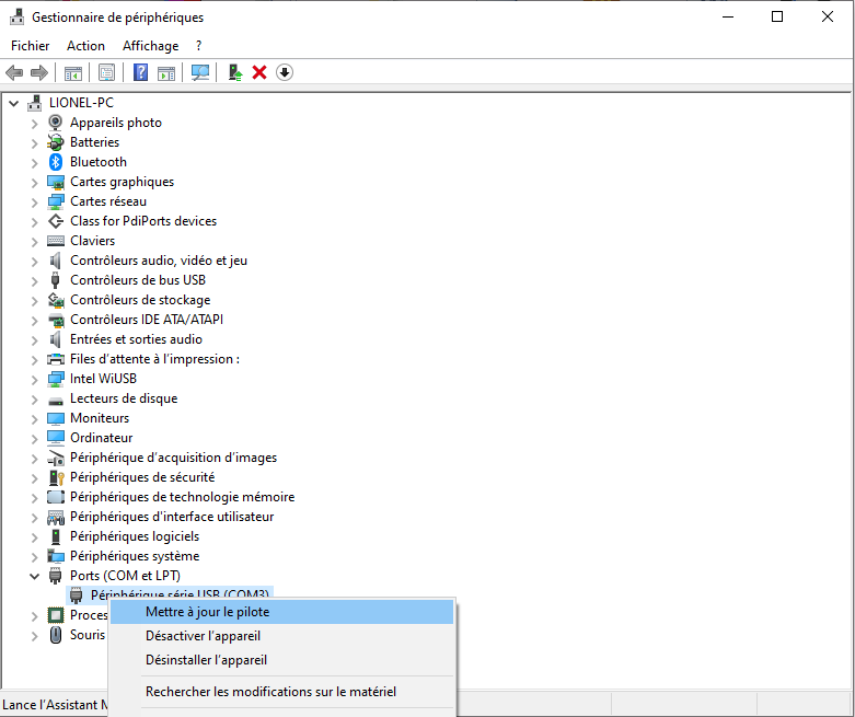
Select " Browse my computer ... " to indicate the path of the folder in which the driver is:
C: \ .... \ KM-CM26-Pilot-WIN-1.0.3 \ lib \ windows \ x64 \
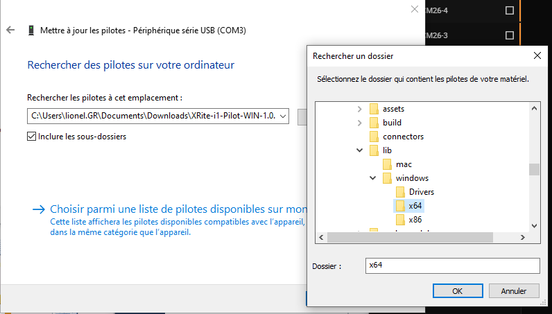
When you have indicated the path, click on " Next "

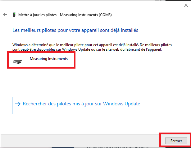
The driver will install, and " USB Serial Device " will become " Measuring Instruments ".
This means that the driver is correctly installed.
Then click on the " Close " button
Modification of the port associated with the KM CM-25/26
To function properly, the serial port associated with the KM CM-25/26 must be COM4.
In the example below, the port assigned by Windows is COM3.
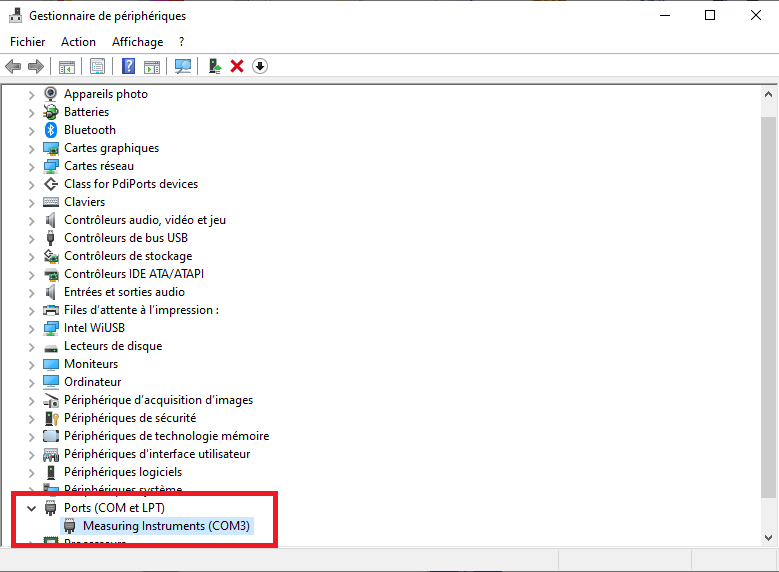
You will have to reassign the COM4 port.
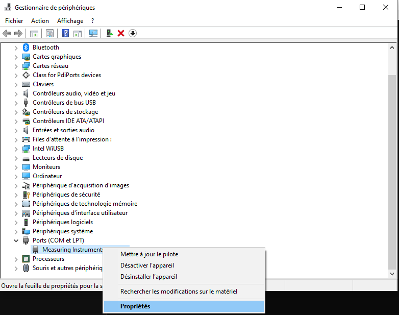
Let's start by right-clicking on " Measuring Instruments ".
Then select " Properties "
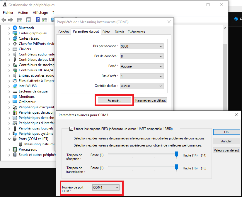
Click on the " Advanced " button to access the advanced parameters for the COM3.
Modify the Port number and select COM4 from the list.
Then click on the " OK " button to validate the modification.
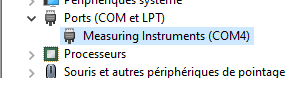
The COM4 port is assigned to the KM CM-25/26
Installation of the KM CM26 Pilot plugin
The installation procedure is described in the procedure: Installing and managing Plugins
To find out more, see the chapter : Installing and managing plugins
Since you have already downloaded the CM-26 plugin in the Dashboard, you can start with chapter 3 of the procedure
Using the KM CM-25/26 with Coraye
With the KM CM-25/26 you have the possibility to perform:
- The measurement of samples with the connected spectrophotometer
- The measurement of samples with the disconnected spectrophotometer
- The measurement of ranges to characterize prints on materials such as glass, metal,
etc ...
To measure samples with Coraye, launch the color capture module.
For more information, see chapter : Capturing a color
Checking the connection
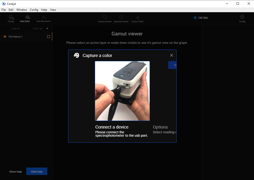
At this step you have the possibility:
- To download the measurements stored in the KM-CM 25/26 or / and
- To use the KM CM-25/26 to capture directly in Coraye, the color samples via a USB connection .
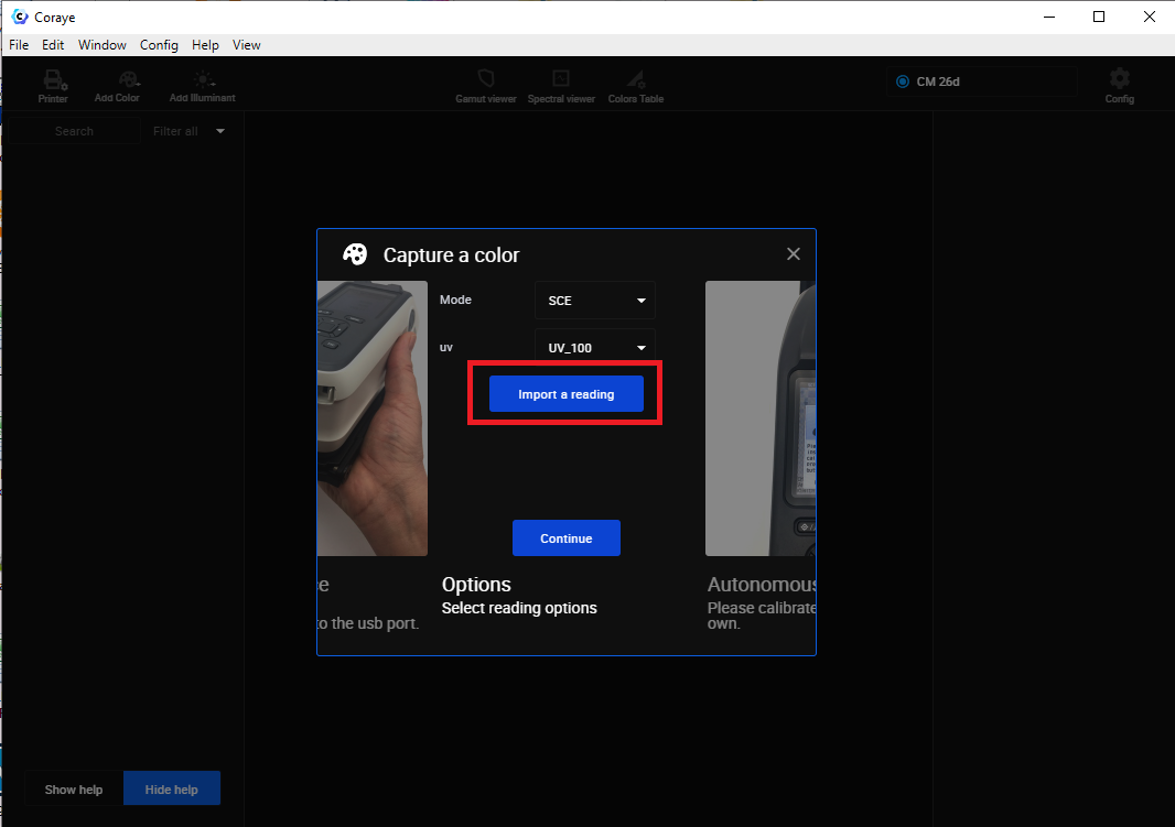
Import of measurements stored in the CM-26
By clicking on the " Import a reading " button, the samples stored in memory will be transferred to Coraye, then the spectrophotometer memory will be erased.
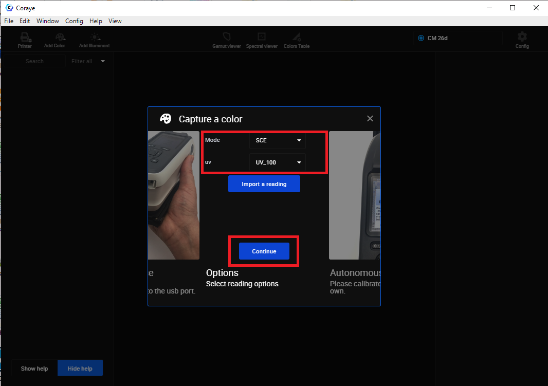
Measurements with the spectrophotometer connected via USB
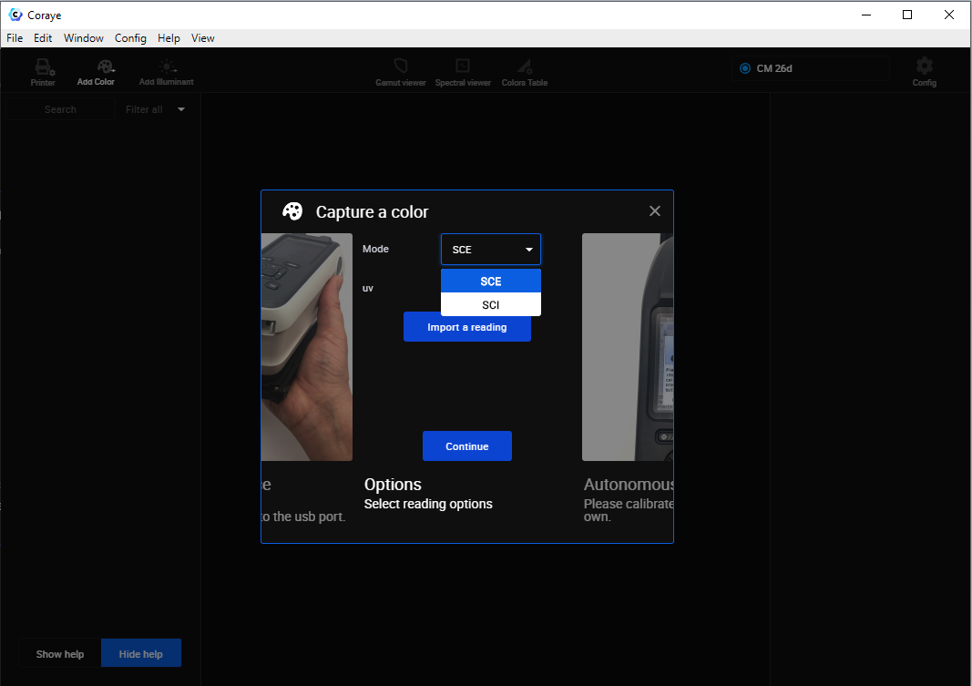
Before clicking on the " Continue " button, remember to check the measurement mode you want to use (SCI or SCE) and also if you want to take into account the incidence of UVs.
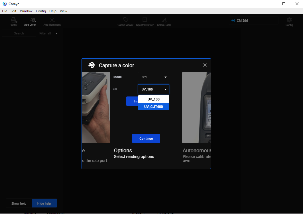
UV mode selection
Selecting SCI or SCE mode
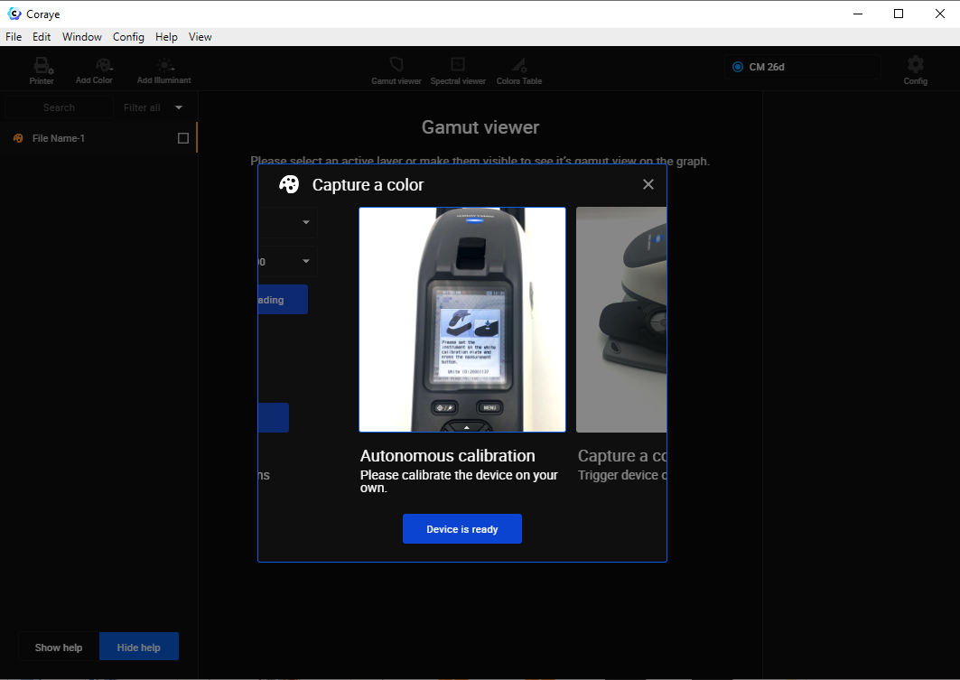
Coraye does not allow you to launch the calibration from its interface.
The calibration is therefore done on the KM CM-25/26 directly.
The procedure for calibrating the KM CM-25/26 is explained in chapter 2 of the manual, section "Calibration".
You will find the links to download these manuals at the end of the chapter.
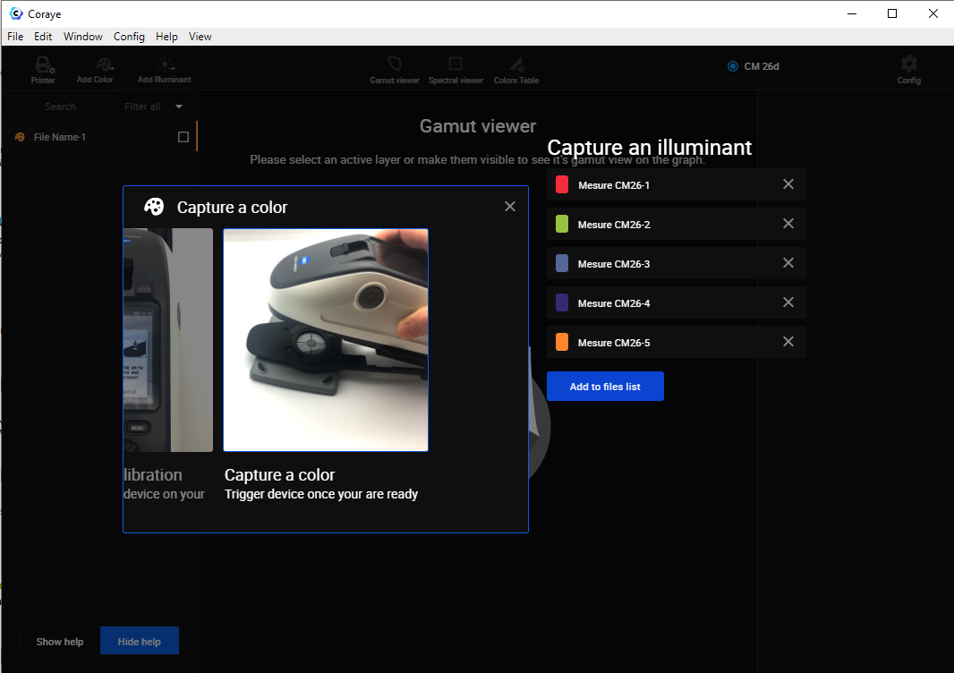
When you have performed the calibration, click on " Instrument is ready " to proceed to sample measurement.
For the rest, refer to the chapter " Capturing a color "
For more information, see chapter: Capturing a color
Import of measurements taken
Creating an ICC profile with a KM SC-25/26
The method of creating a profile with a KM SC-25/26 is identical to other spectrophotometers.
All you have to do is follow the " Create a profile " procedure.
To find out more, see the chapter: Creating a profile from a standard test pattern
Do not forget to select the right reading modes
The measurement of the range being done patch by patch, it would be a shame to notice at the end of the measurement, that you made a mistake in choosing the SCI / SCE mode or UV100 / UV CUT400 especially after measuring 1000 patches ...
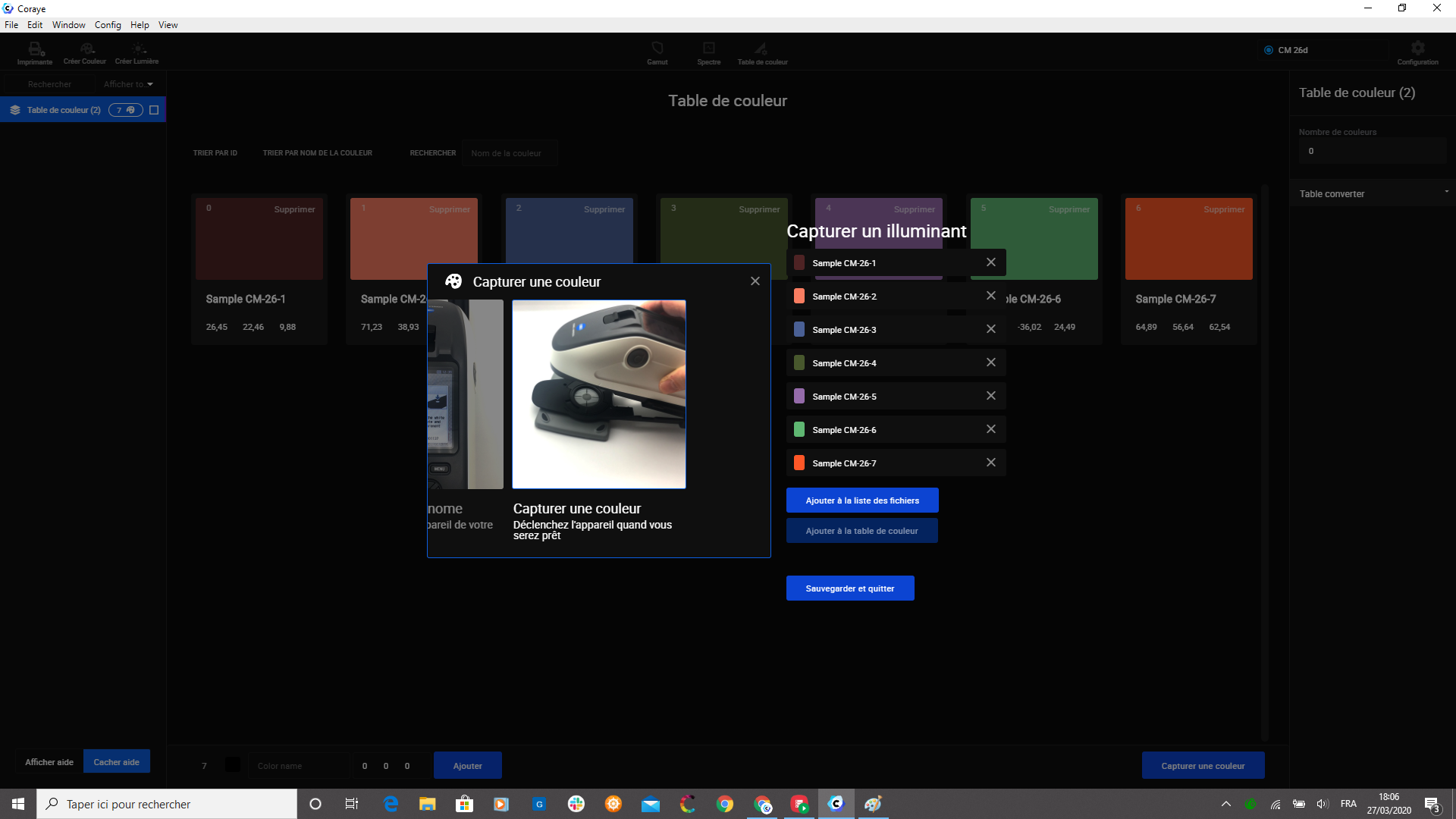
Measuring samples in a "Color Table"
The method for adding samples to a color table is the same as for other spectrophotometers.
For more information, see chapter: Color table
KM-25/26 User Manual
User manuals can be downloaded from the following addresses:
In English: https://www.konicaminolta.com/instruments/download/instruction_manual/color/pdf/cm-26dg_instruction_eng.pdf
In German: https://www.konicaminolta.com/instruments/download/instruction_manual/color/pdf/cm-26dg_instruction_deu.pdf Other languages: https://www.konicaminolta.com/instruments/download/instruction_manual/color/index .html
SCI / SCE mode with or without UV
SCI Mode: Specular Component Included
SCE Mode: Specular Component Excluded
Link to a Konica Minolta blog explaining the difference between SCI and SCE mode: https://sensing.konicaminolta.us/blog/specular-component-included-sci-vs-specular-component- excluded-sce / Mode UV 100: Measurement with UV source to react optical brighteners
CUT400 UV mode: Measurement with filtered UV below 400 nm to ignore optical brighteners
Example of measurement carried out on a glossy Chromaluxe plate
A gray sample was measured with the four reading combinations: The display of the reflectance curves makes it possible to visualize the difference in measurement between the different modes:
- SCI - UV100 (Red)
- SCE - UV100 (Blue)
- SCI - UV CUT400 (Orange)
- SCE - UV CUT400 (Cyan)
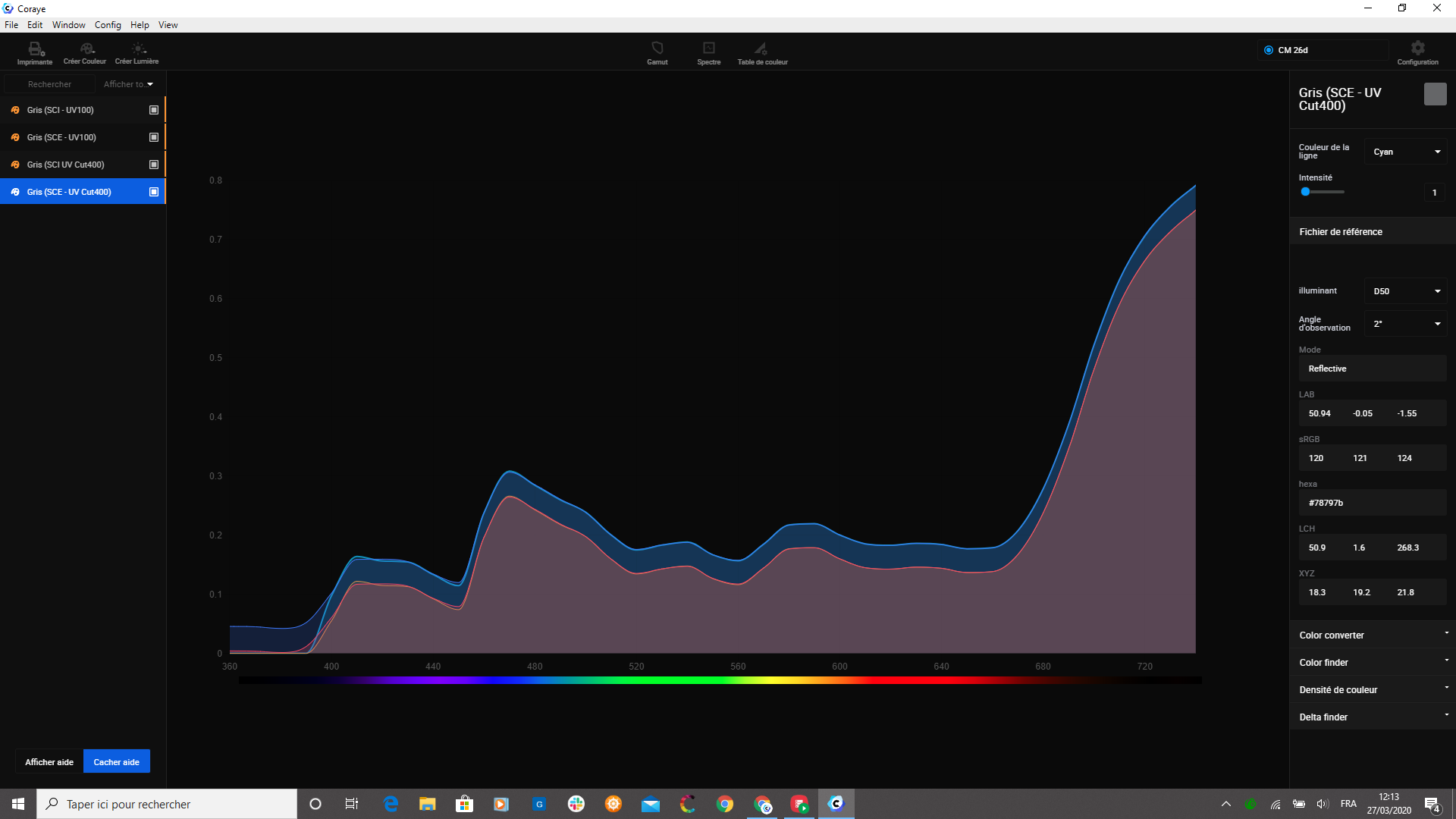
Note: On the right column you can directly obtain the information associated with the selected sample.