Plugins
- Barbieri
- Barbieri LFP qb
- Barbieri LFP qb Sensing Unit
- Barbieri Spectropad
- Konica Minolta CM-26 CM-25
Barbieri
Each spectrophotometer is suitable for a number of types of material.
Barbieri spectrophotometers will allow you, with Coraye, to measure transparent materials, fabrics, and other special supports
Barbieri LFP qb
For more information, see chapter: Barbieri LFP qb
Barbieri LFP qb Sensing Unit
For more information, see chapter: Barbieri LFP qb Sensing Unit
Barbieri SpectroPad
For more information, see chapter: Barbieri Spectropad
Barbieri Gateway & Chart Generator software
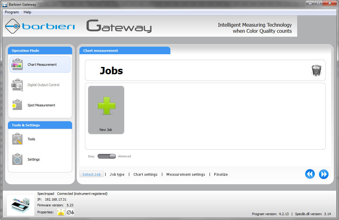
For more information, see chapter: Barbieri Gateway & Chart Generator
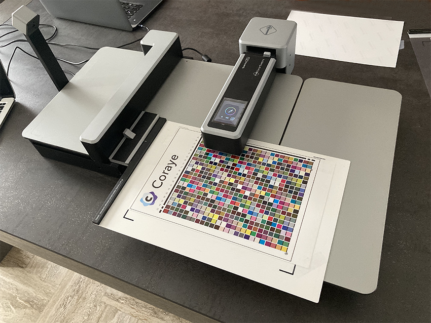
Barbieri LFP qb
The Barbieri table is a high-end solution for taking measurements on transparent media, fabrics and thick media up to 2 cm
Introduction
The Barbieri LFP qb is compatible with the Calibration & Characterization and Print Control modules.
Product sheet: https://www.barbierielectronic.com/project/spectro-lfp-qb/
Manual: https://www.barbierielectronic.com/knowledge-base/#Operating_manuals
USB or RJ45 network connection
Coraye gives you the possibility to connect your Barbieri LFP spectrophotometer via the USB port or via the RJ45 network connection.
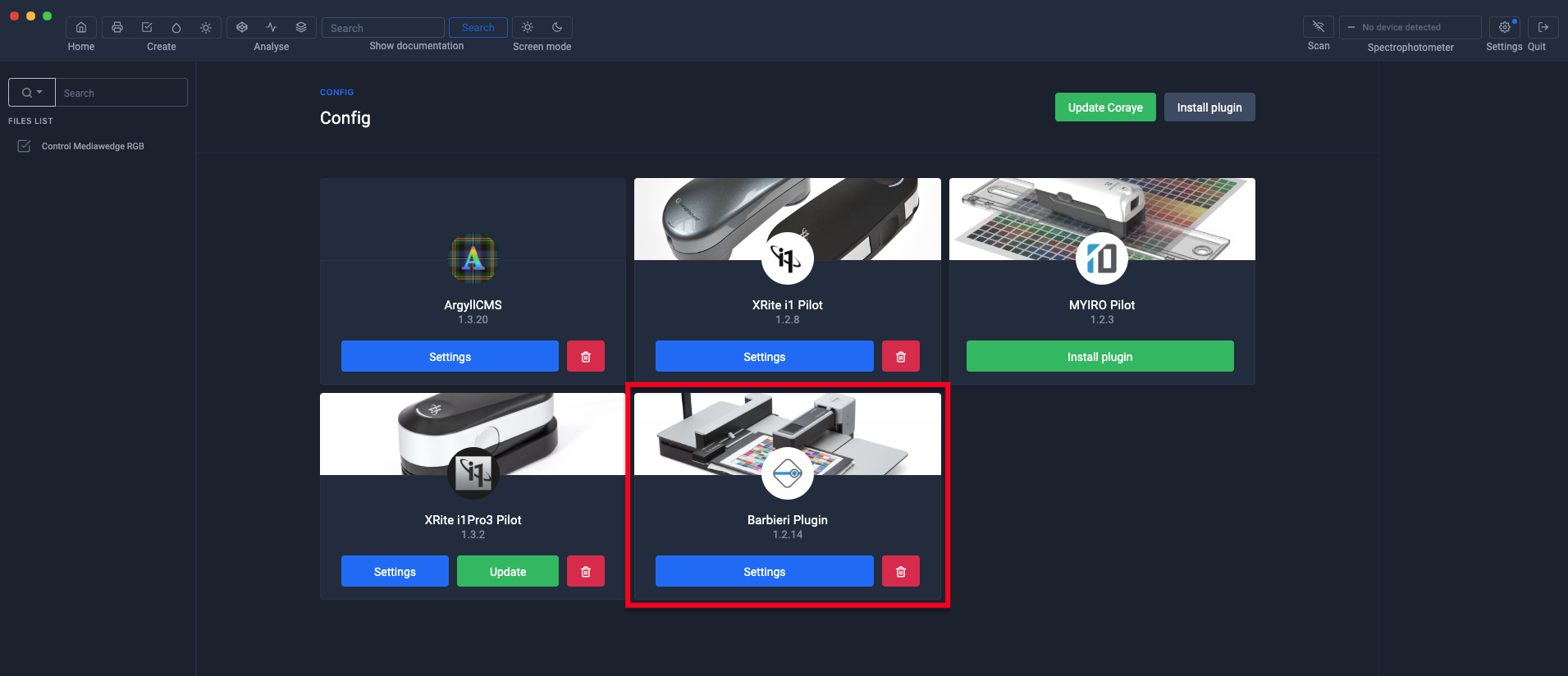
First of all, make sure that the Barbieri plugin is installed
To find out more, see the chapter: Installing and managing plugins
USB connection
When your Barbieri LFP qb is connected via usb, it will be detected and displayed at the top right in the Coraye window. You won't have to do anything else.

RJ45 network connection
If you choose to connect your Barbieri LFP qb to a network via an RJ45 connection, it is necessary to indicate the Barbieri IP address.
First step: Retrieve the IP address of the Barbieri:
Press the part located at the top right of the touch screen of the measuring head
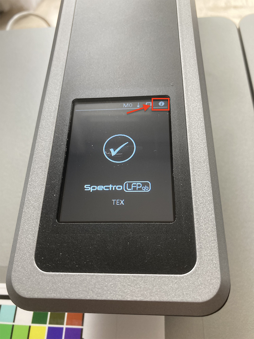
The IP address appears on the screen
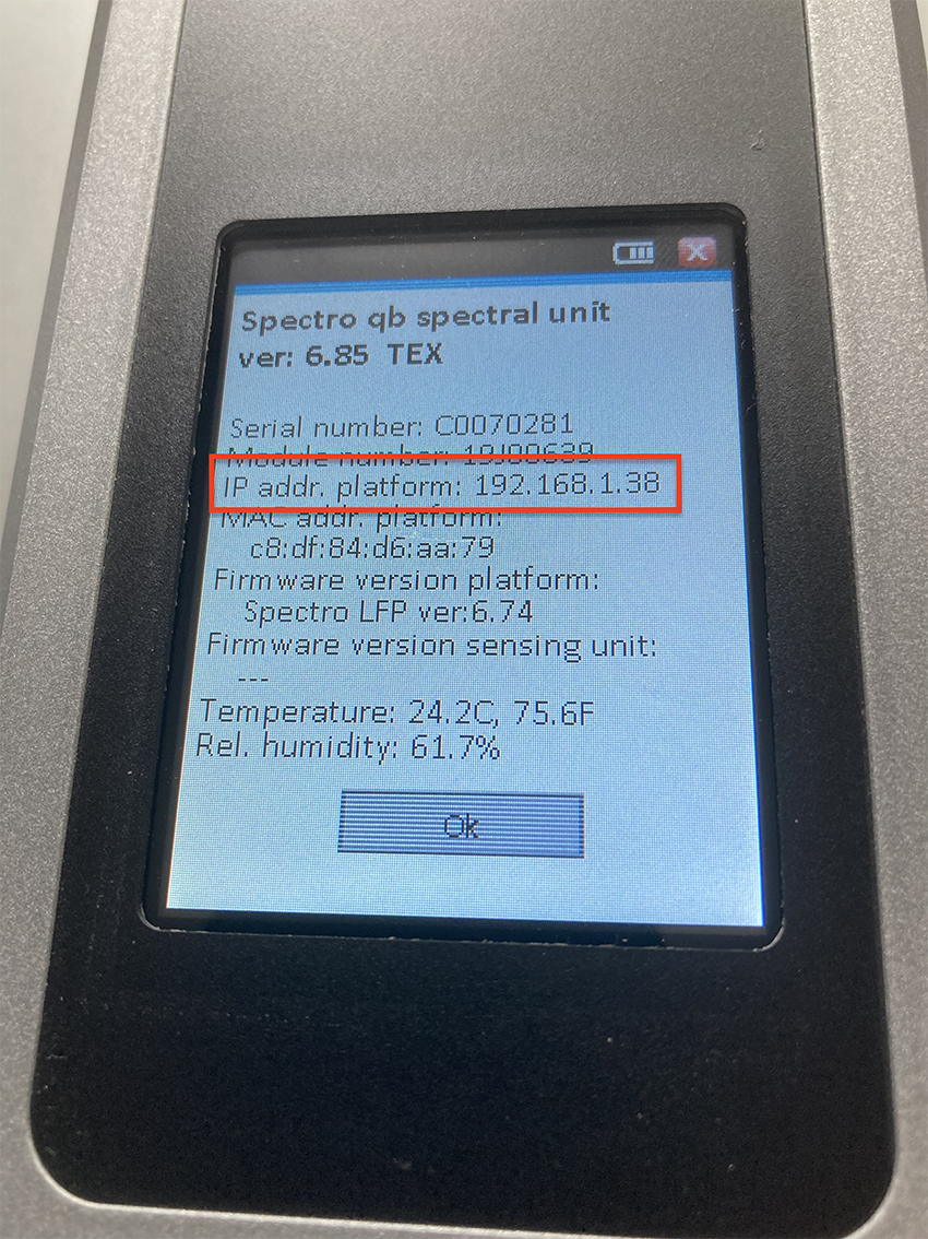
If the IP address does not appear, make sure the RJ45 cable is properly connected to the Barbieri and to the network, then restart the Barbieri
Second step: transfer the IP address in Coraye
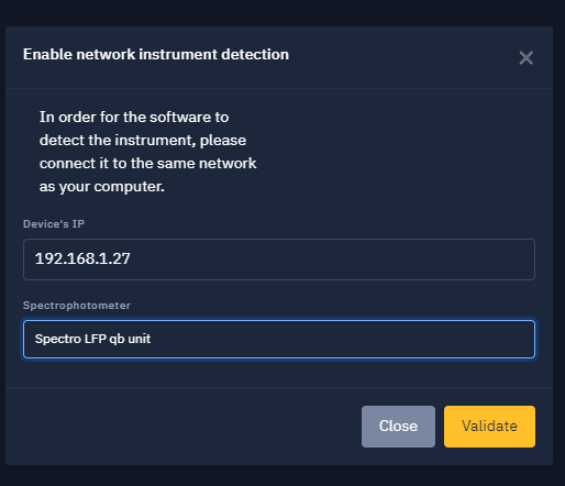
Click on the "Enable network instrument detection" button located at the top right of the Coraye window

In the window that appears, enter the IP address of the Barbieri (Ex: 192.168.1.38) then select the model of the spectrophotometer (In our example: Spectro LFP qb).
Click on the "Validate" button

Congratulations, your Barbieri spectrophotometer is ready for use.
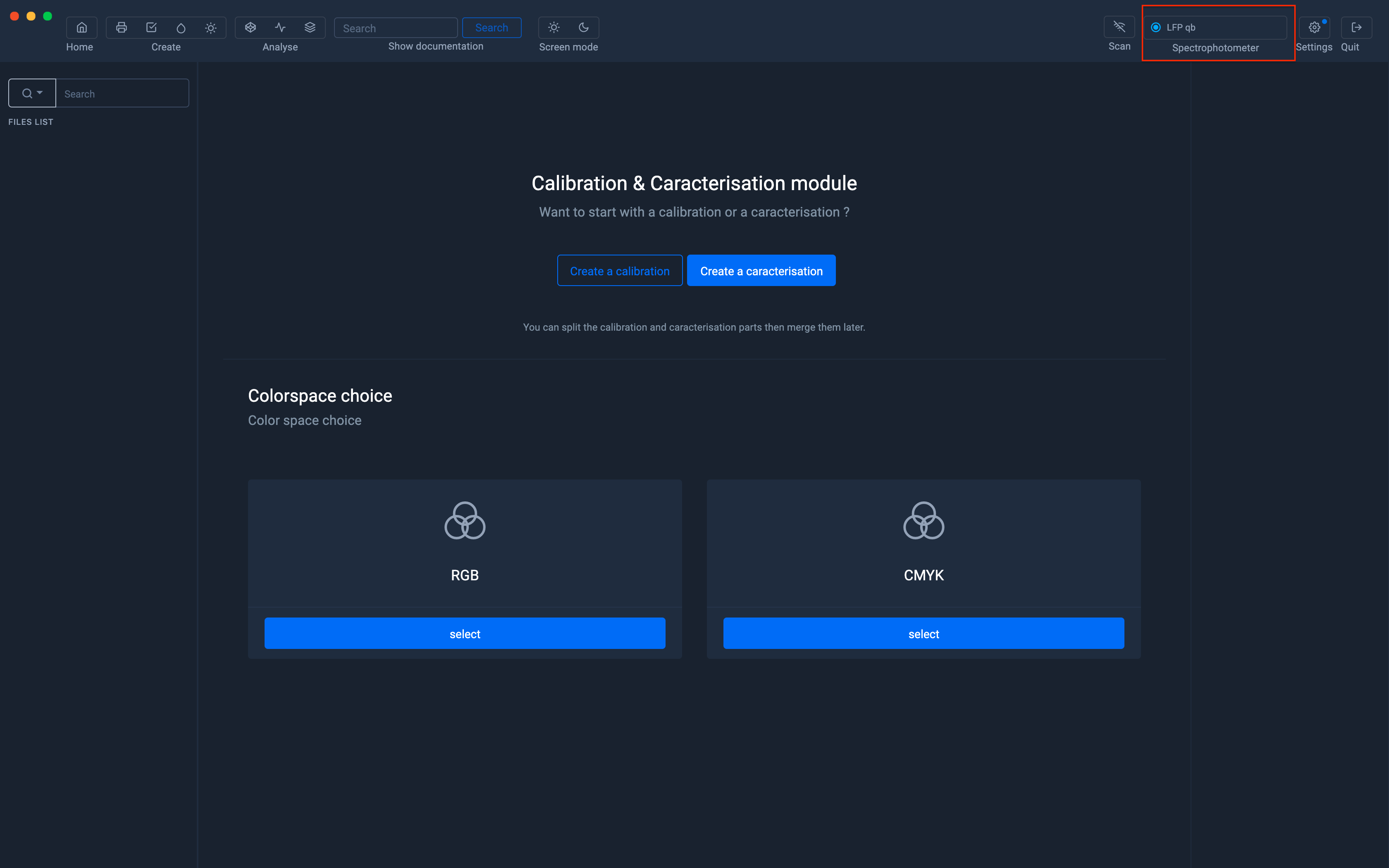
Creation of an ICC profile
In order to illustrate the use of the Barbieri LFP with Coraye, we will use the icc profile creation module.
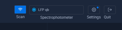
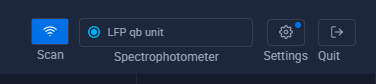
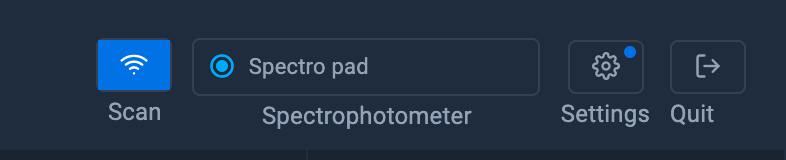
When the Barbieri LFP table is recognized by Coraye, her name is displayed in the top right corner.
In this example we will measure an IT8.7-4 Random range

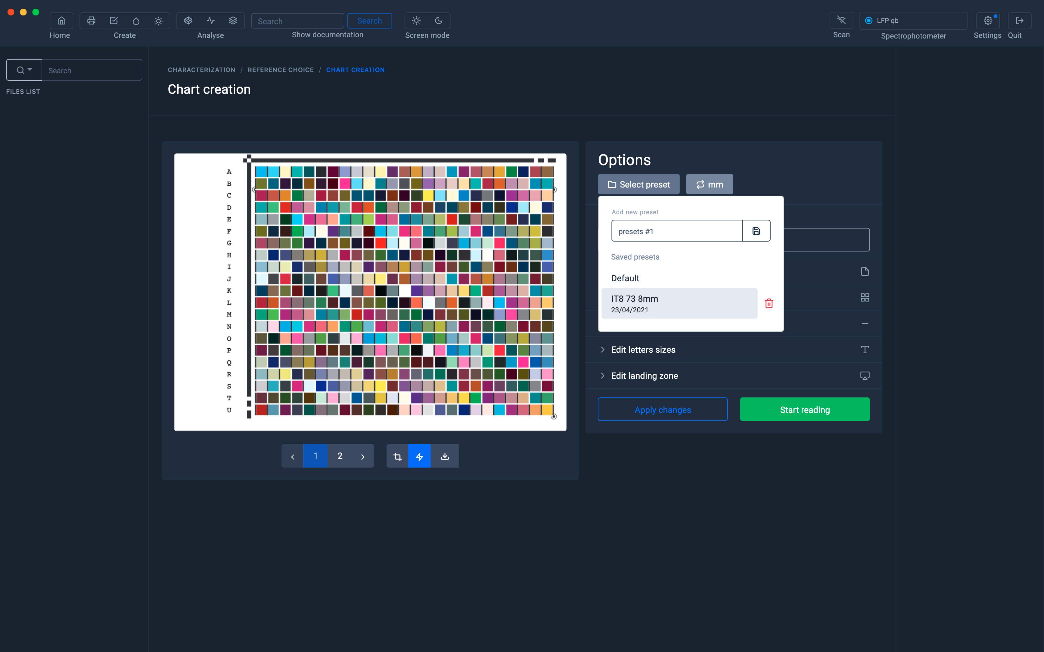
Customization of charters
From the list of spectrophotometers, select the Spectro LFP qb to convert the staff to the correct format.
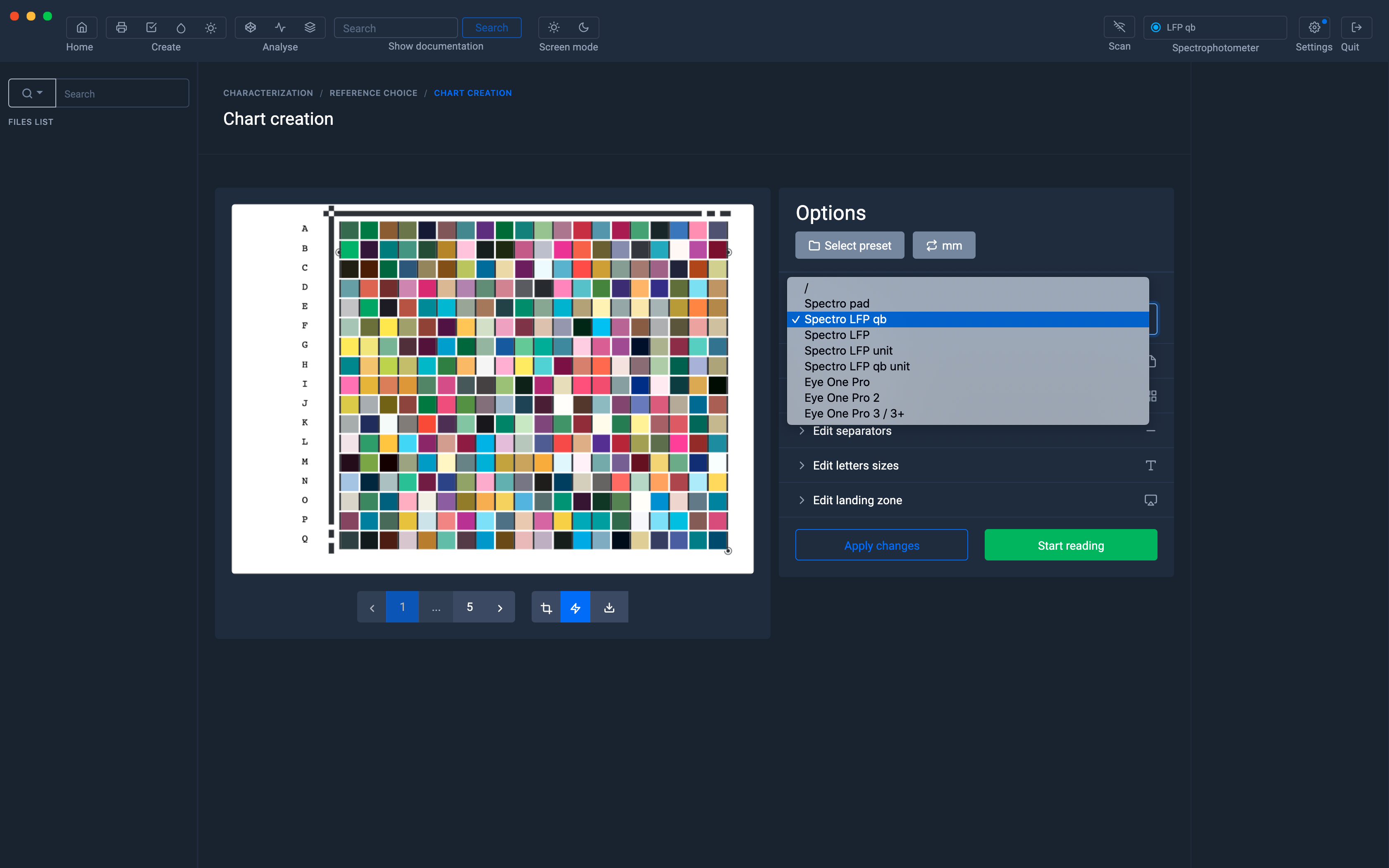
But it is also possible to save Presets with personalized parameters.
To find out more, see the chapter: Customizing charts
Export the test pattern in Tiff or PDF format to print it
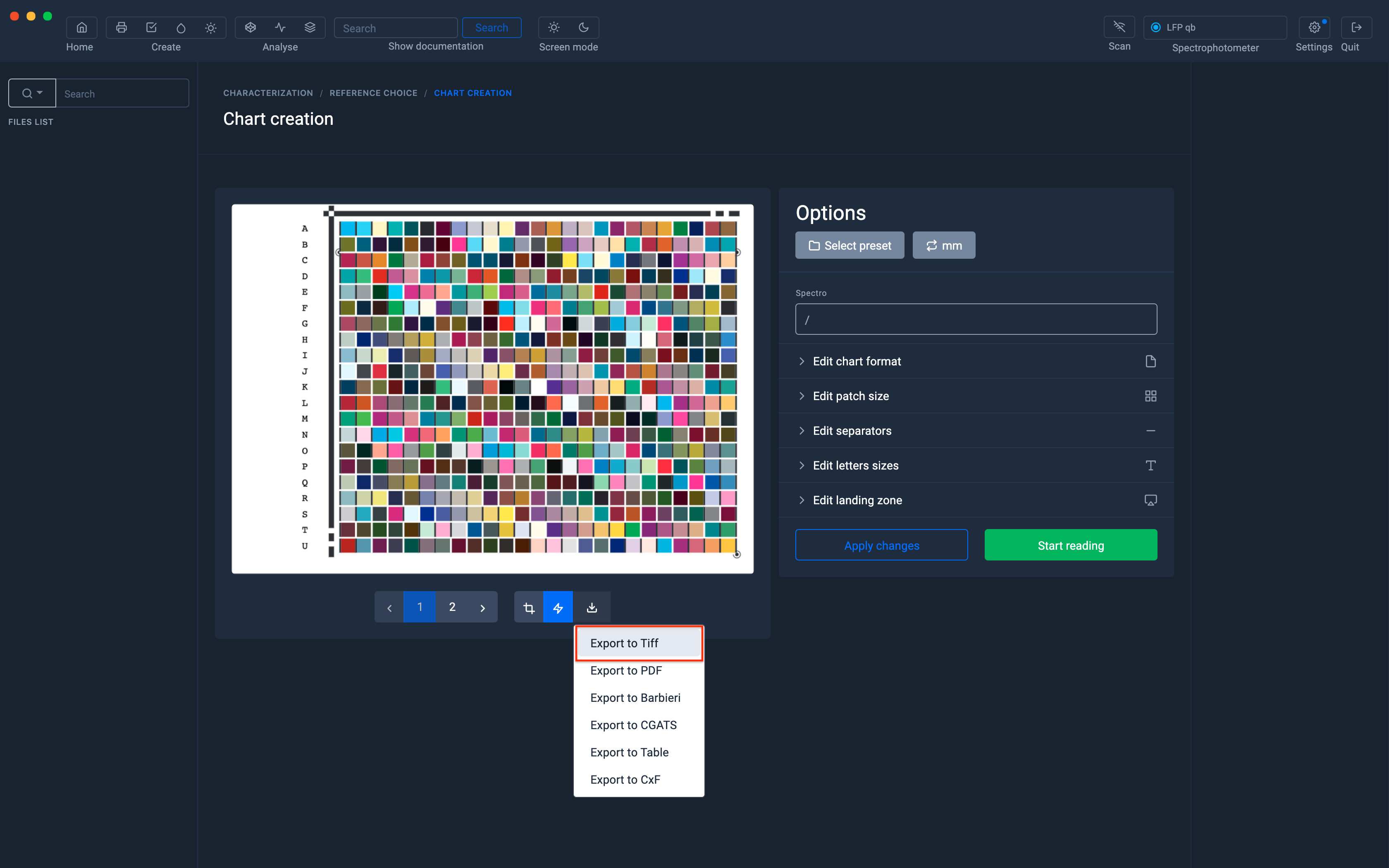
The test pattern printing conditions depend on the profile you want to achieve, we will not deal with this subject in this tutorial.
However, below is a link to create RGB profiles from a simple driver:
For more information, see the chapter: Printing an RGB test pattern
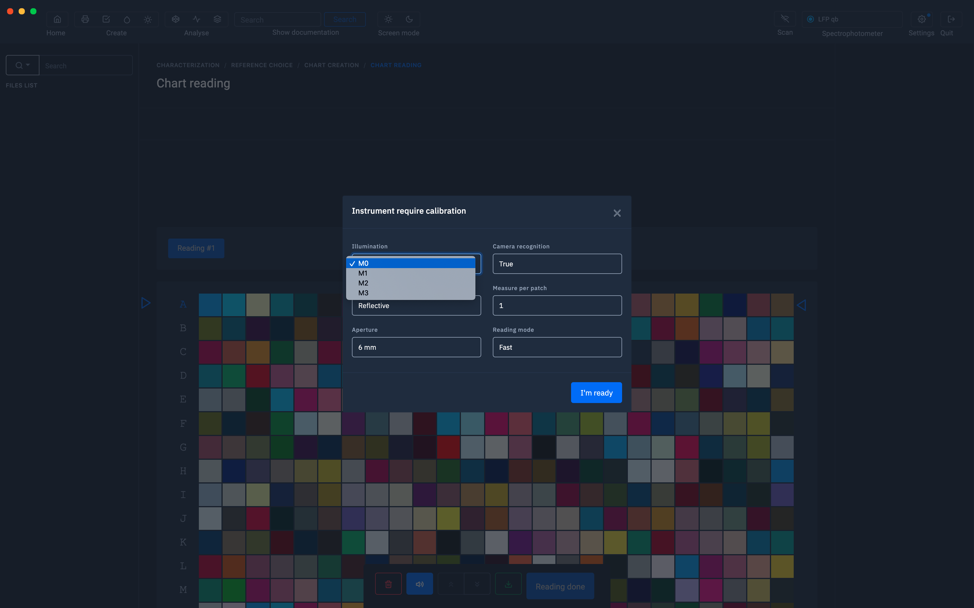
Measurement options
Measuring conditions
The Barbieri LFP supports M0, M1, M2 and M3 modes (polarizing filter option).
UV filter and polarization filter: The UV filter is already included in the instrument and is activated by selecting measurement condition M2.
The optional polarization filter available for reflection measurements can be replaced by simply removing with your finger first the reference white on the spectral unit, then the aperture ring and replacing it with the filter cover. polarization.
The aperture ring is held by a magnet:
Measurement condition M2 (UV filter) is used to eliminate the effect of optical brighteners.
The measurements correspond to measurement condition M2 of ISO 13655: 2017
The polarization filter is used when measuring shiny surfaces.
The measurements correspond to measurement condition M3 of ISO 13655: 2017
Measurement of fluorescent inks in daylight Fluorescent inks, as understood here and used in the printing industry, are inks which absorb light in UV and visible wavelengths and retransmit at longer wavelengths in the visible spectrum and manifest as color.
This effect already occurs under daylight conditions.
The Spectro LFP qb is able to illuminate in daylight using the M1 measurement condition and is therefore able to stimulate this fluorescent effect.
The re-emitted light is added to the normal reflected light,which gives spectral curves which exceed 100% remission.
The Spectro LFP qb is able to automatically extend its dynamic range when using the UpDown mode and is therefore capable of measuring fluorescent inks that exceed the emitted light by more than 200%.
Therefore, to correctly measure fluorescent inks: use measurement condition M1 use UpDown measurement mode save spectral data in measurement files
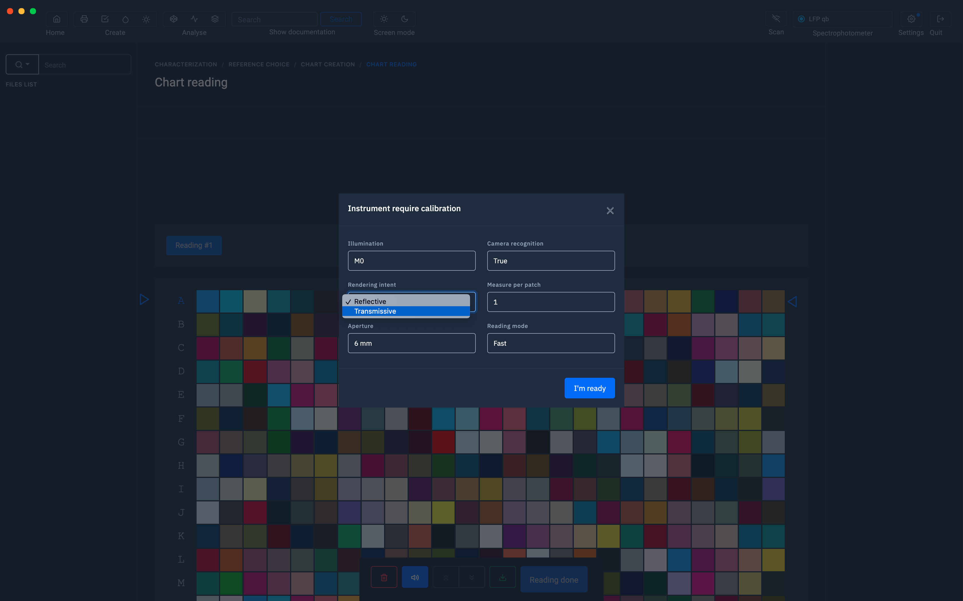
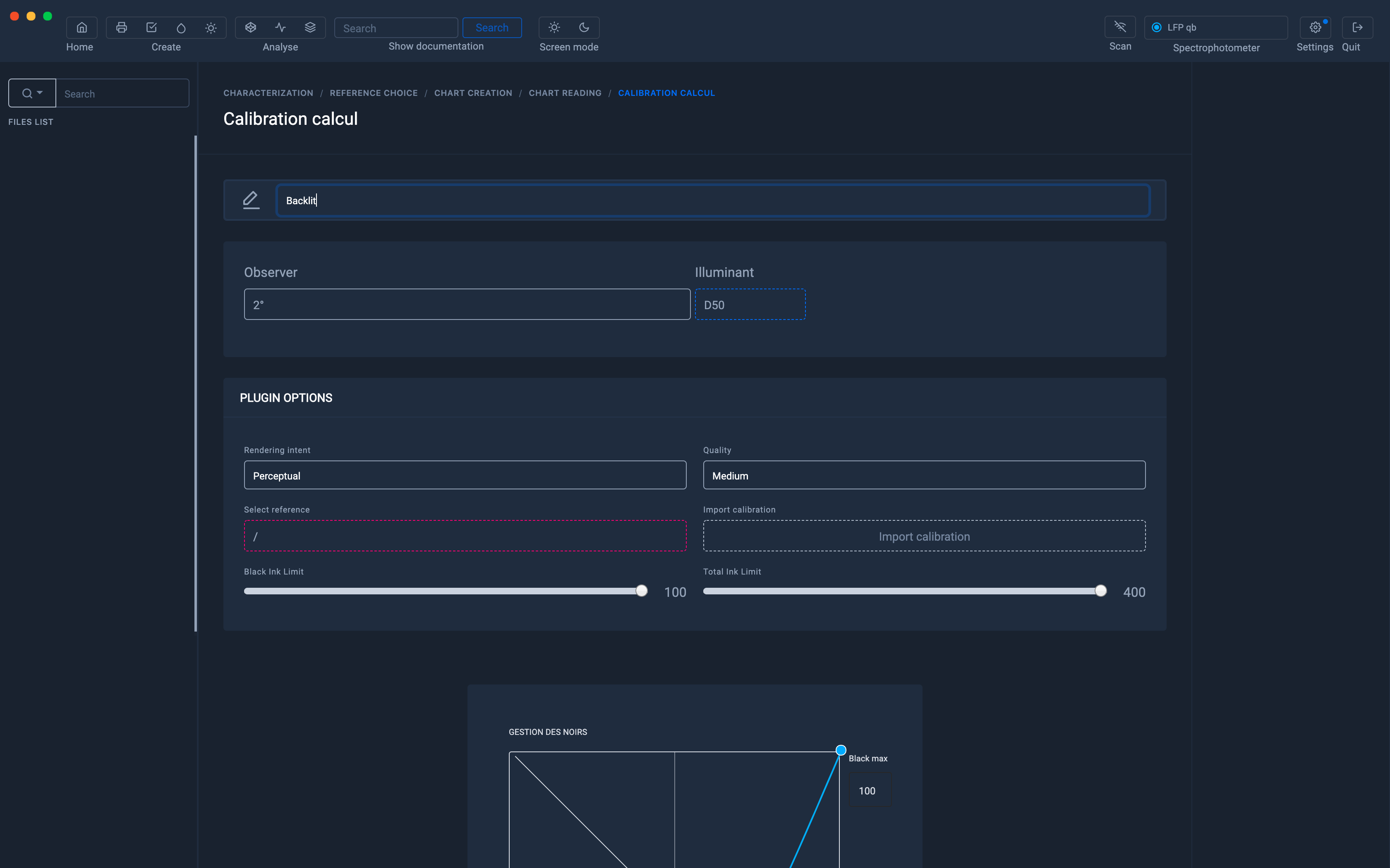
Measurement in opaque or transparent mode
Even if the majority of the measurements are carried out in reflection mode, the most interesting possibility of the Barbieri LFP, is to be able to measure media transparently, such as Backlits.
Choice of opening
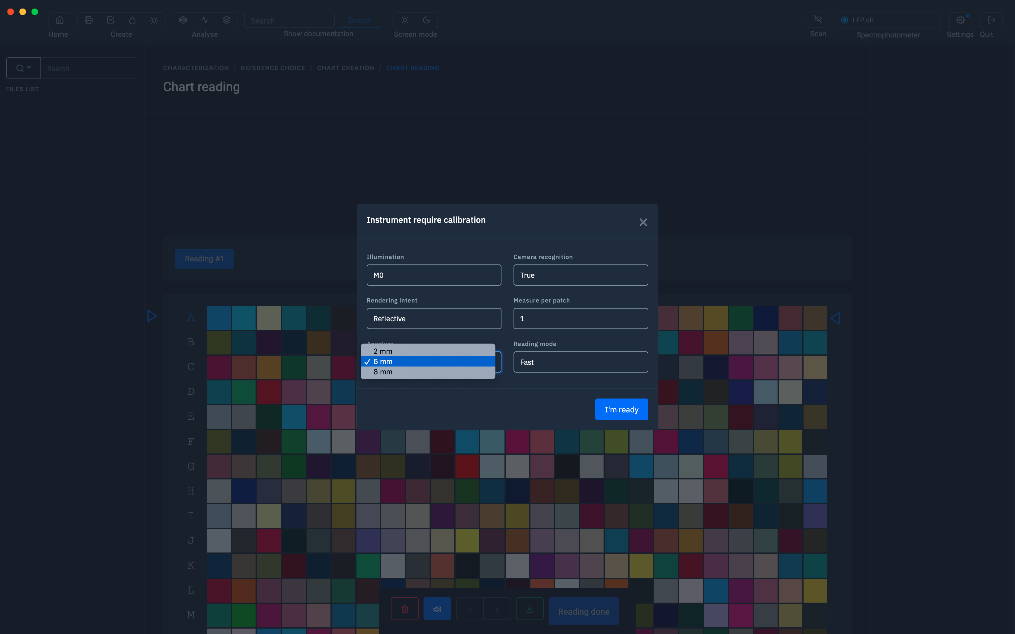
The Spectro LFP qb spectral unit is equipped with a selectable measuring aperture. Switching occurs automatically by the pilot (manual switching is only supported in spot mode when the spectral unit is used detached from the platform).
The aperture size is valid for reflection and transparency measurements.
The selected aperture is shown on the display.
The small opening corresponds to an opening of 2 mm, the large opening to 8 mm.
The large aperture should be used with structured materials or if the print resolution is less than 120 dpi.
When using the large aperture, make sure your target to be measured has plates of 10mm or greater.
The recommended patch size is as follows:
2mm opening: 5mm or more 6mm
opening: 10mm or more 8mm
opening: 12mm or more
Recognition of the position of the patches by camera (LFP qb only)
This option is useful for measuring test marks made on textiles.
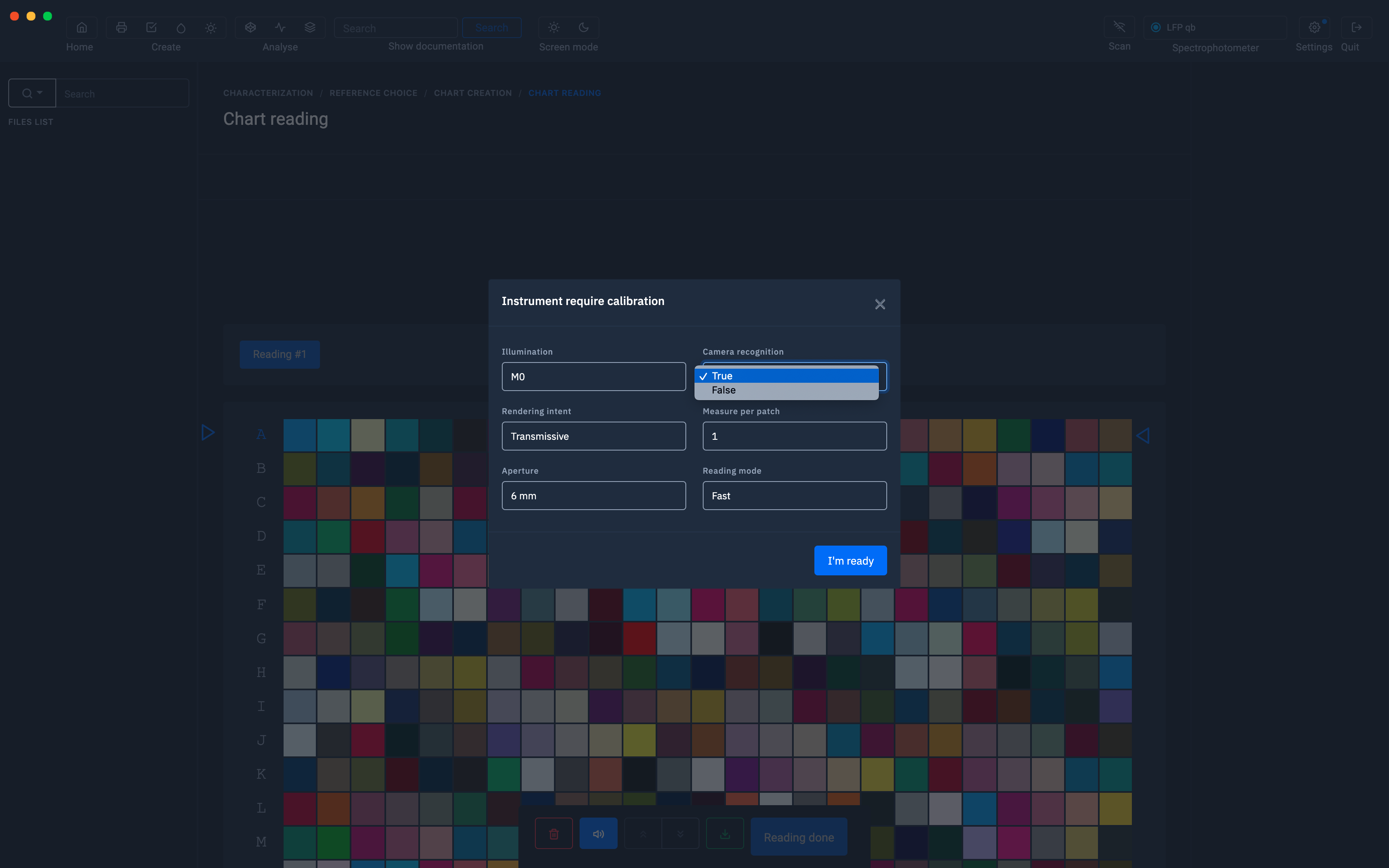
When the "TEX" option (textile activation) is activated on the instrument, the detection unit will capture an image of the inserted chart, measure and analyze it and provide information on the size of the graphic, the typical graphic. , graph position, etc.
Camera recognition on Barbieri LFP qb

Number of measures per patch
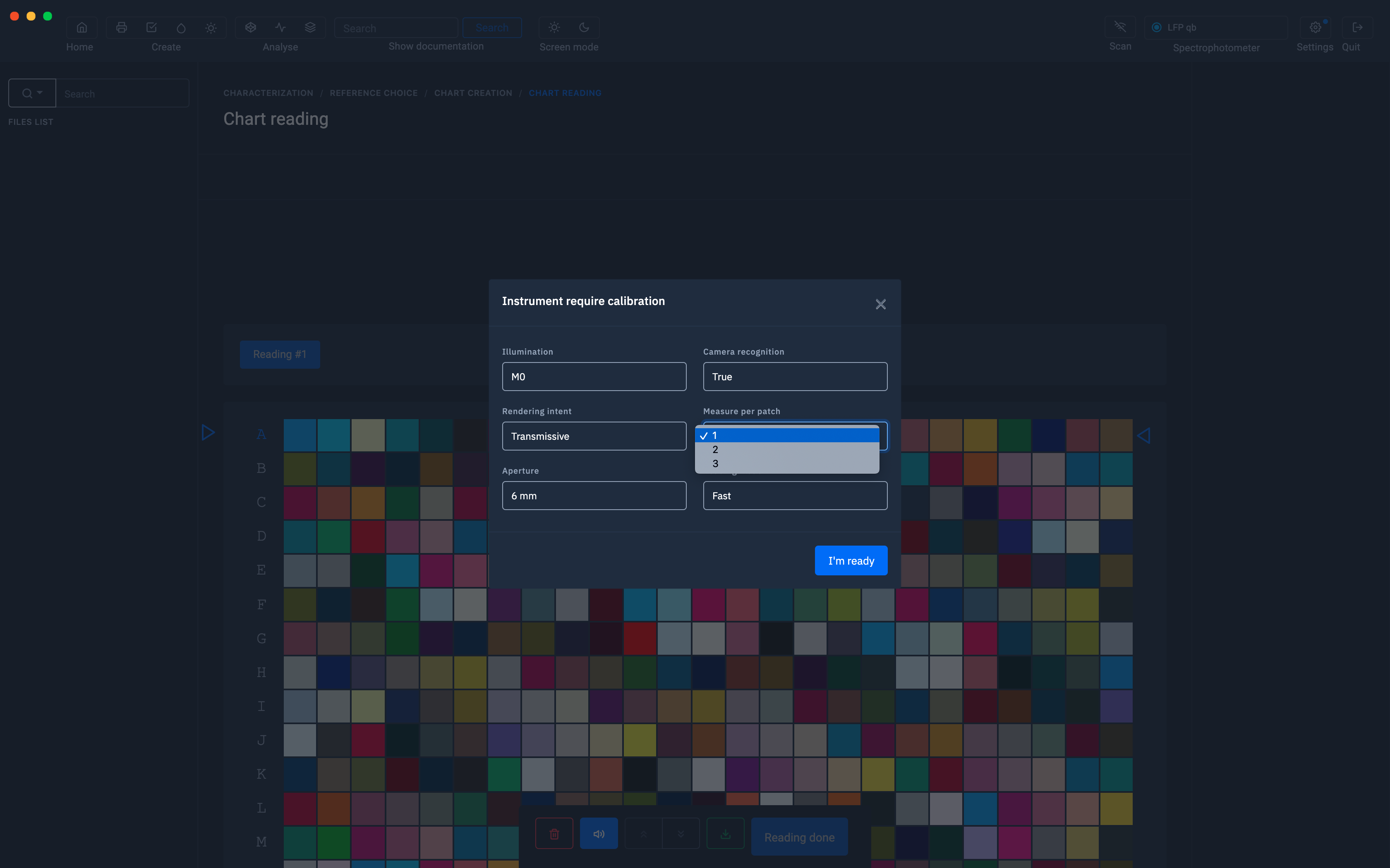
Reading mode
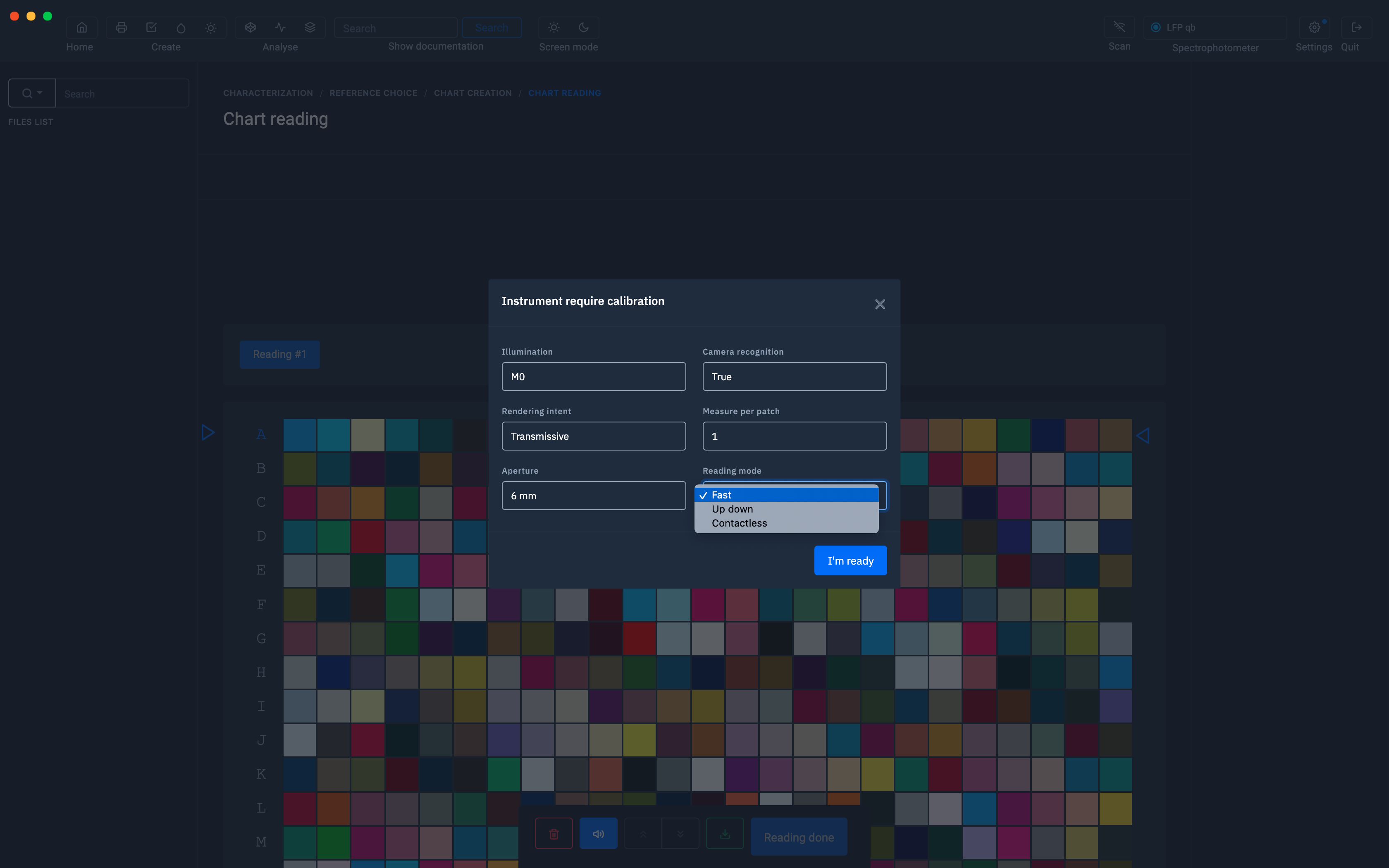
The Spectro LFP qb supports three measurement modes:
1. Up-down
mode In up-down mode, the measuring head of the instrument moves up and down between each measurement. Use this mode for sensitive materials to avoid scratches on the target surface. This mode also gives the most accurate measurements and is used to measure fluorescent inks.
2. Fast Mode (Default)
Fast measurement mode is the default mode of the Spectro LFP qb.
In this mode, the measuring head rests on the target and the surface is scanned.
3. Non-contact
mode The non-contact mode is similar to the fast mode above except that the measuring head does not touch the surface of the target.
This measuring mode is suitable for sticky and sensitive materials.
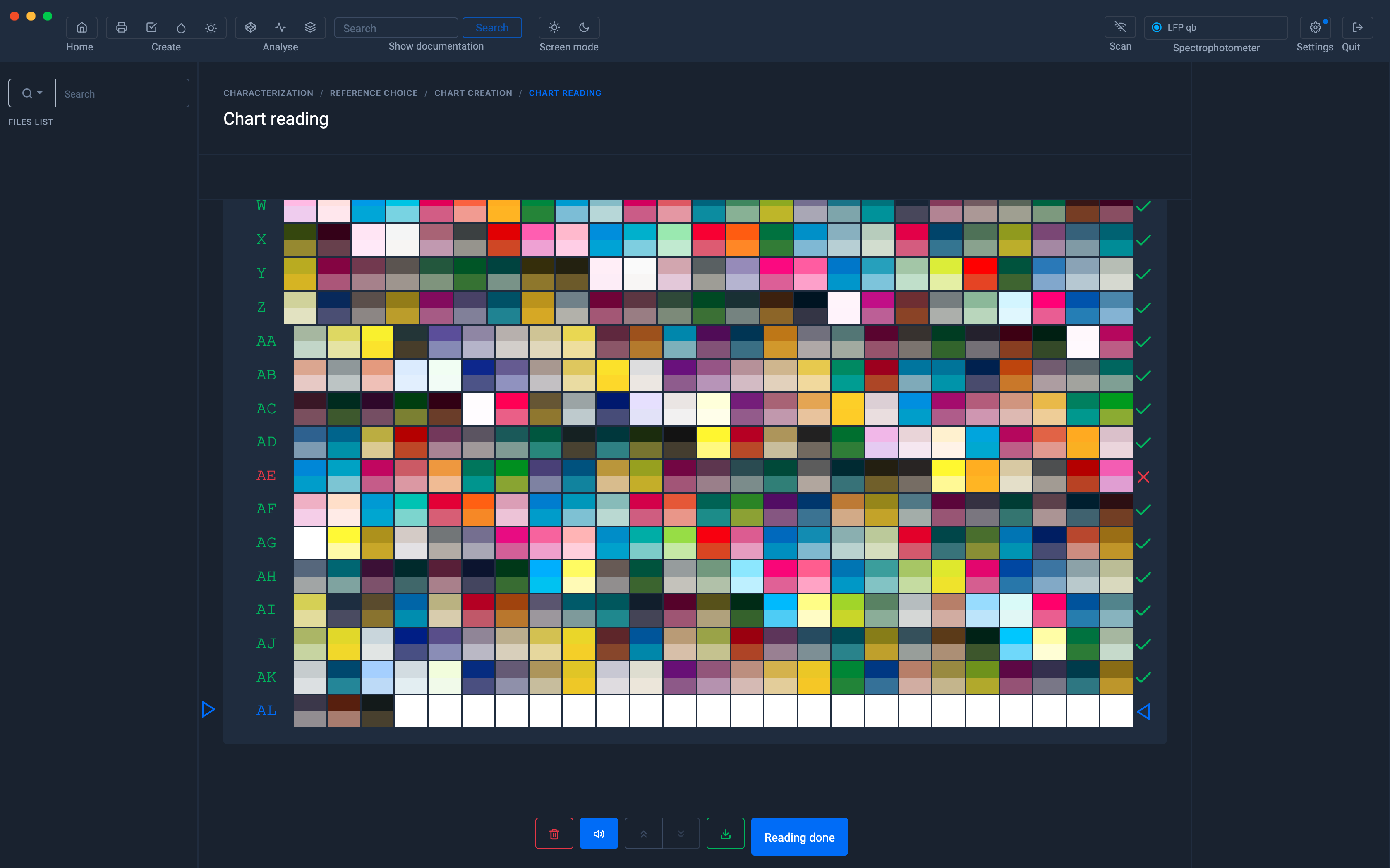
Multi page measurement
When the staff contains many patches, it is often necessary to measure several sheets in a row.
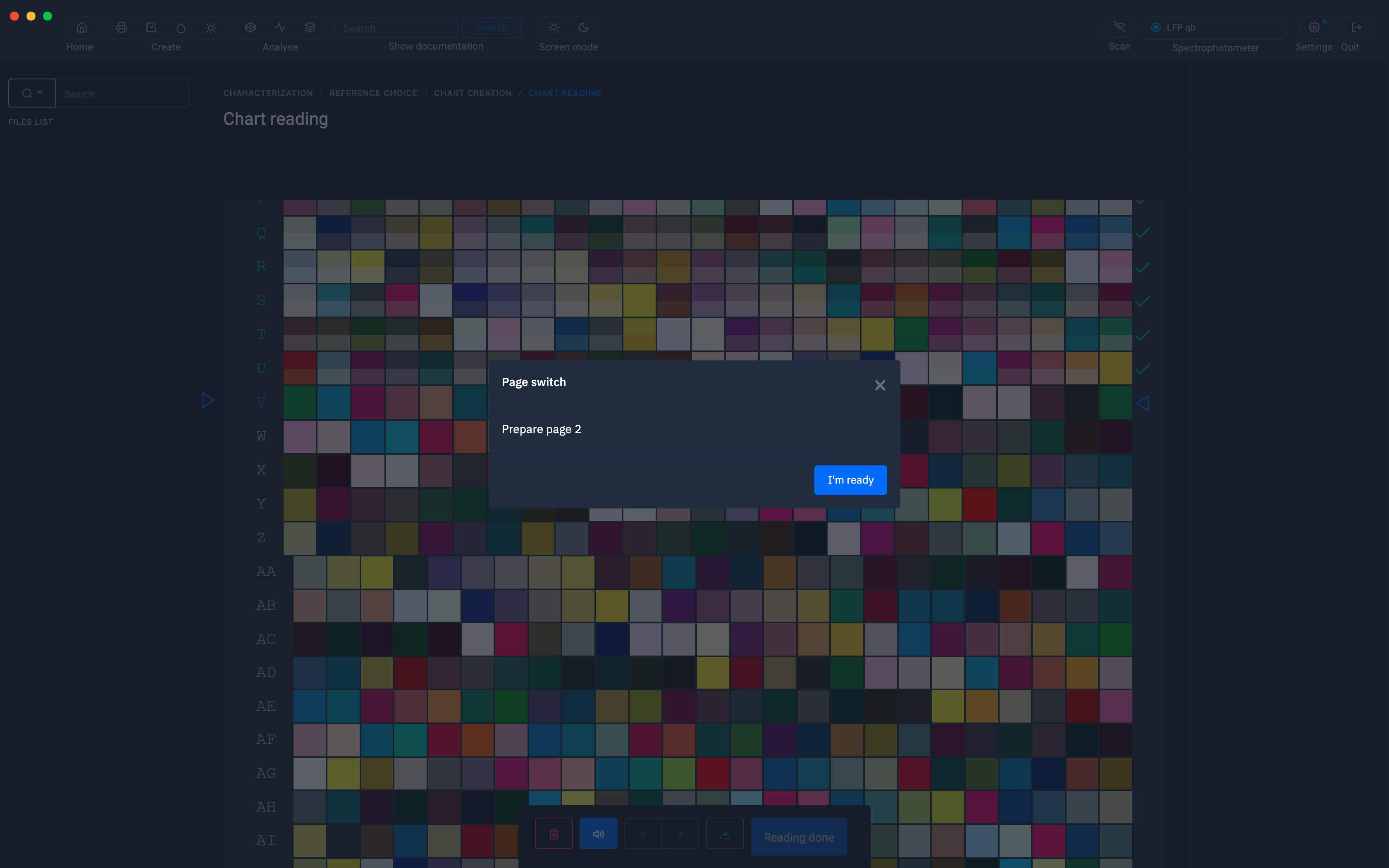
Once the measurement is complete, click on " Reading completed "
Before clicking on "Reading finished", remember to save your measurement
Creation of the ICC profile
The procedure for creating an icc profile remains the same as for other instruments.
To find out more, see the chapter: Creating a profile from a standard test pattern
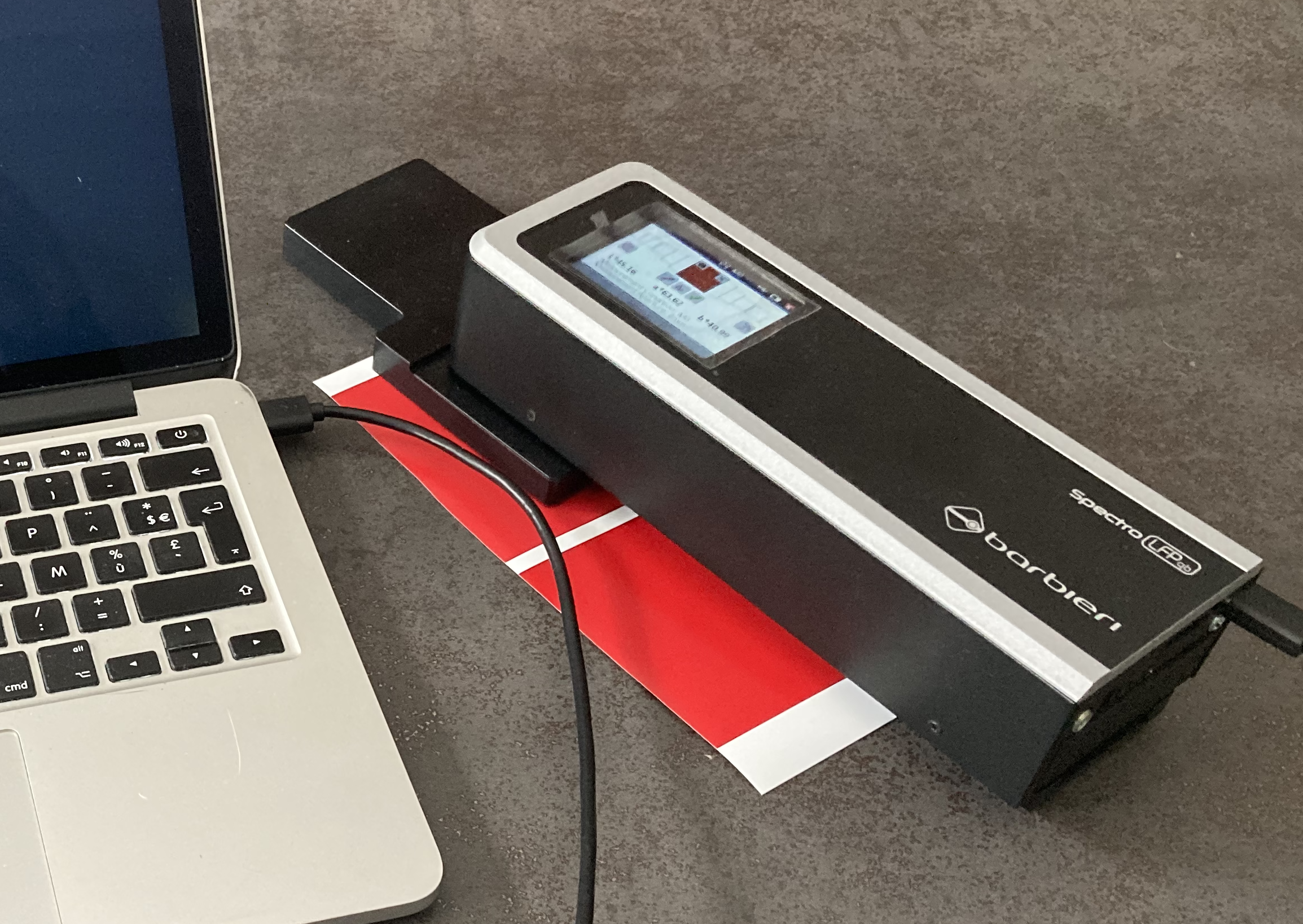
Barbieri LFP qb Sensing Unit
The Barbieri LFP qb measuring unit is detachable and allows measurements with the Color Capture module.

Point measurement
The spectral unit can be detached from the platform to use it as a manual device for point measurements. Turn off the platform and detach the spectral unit by releasing the button on the back of the spectral unit.
Turn on the spectral unit by pressing the button on the back.
The screen will display the following content:
The "Calibrate device" button performs an automatic device calibration by automatically inserting the internal reference blank and performing the calibration.
USB connection or Wi-Fi network
Coraye gives you the possibility to connect your Barbieri LFP spectrophotometer via the USB port or via the Wi-Fi network connection.
First of all, make sure that the Barbieri plugin is installed and that the Sensing Unit is switched on.
To find out more, see the chapter: Installing and managing plugins
USB connection
When your Barbieri LFP qb Sensing Unit is connected via usb, it will be detected and displayed at the top right in the Coraye window.
You won't have to do anything else.
WIFI network connection
If you choose to connect your Barbieri LFP qb Sensing Unit to a network via a WIFI connection, you must enter its IP address.
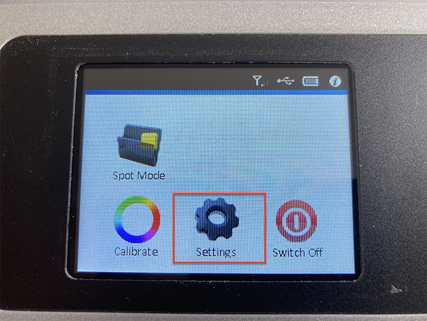
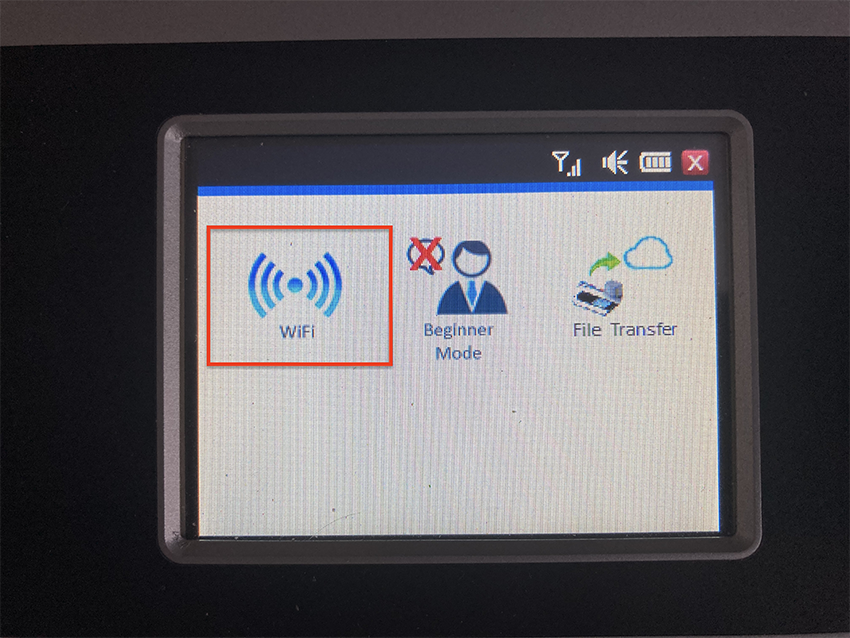
Select the "Settings" gear icon
Select the "Wi-Fi" icon

The IP address appears on the screen
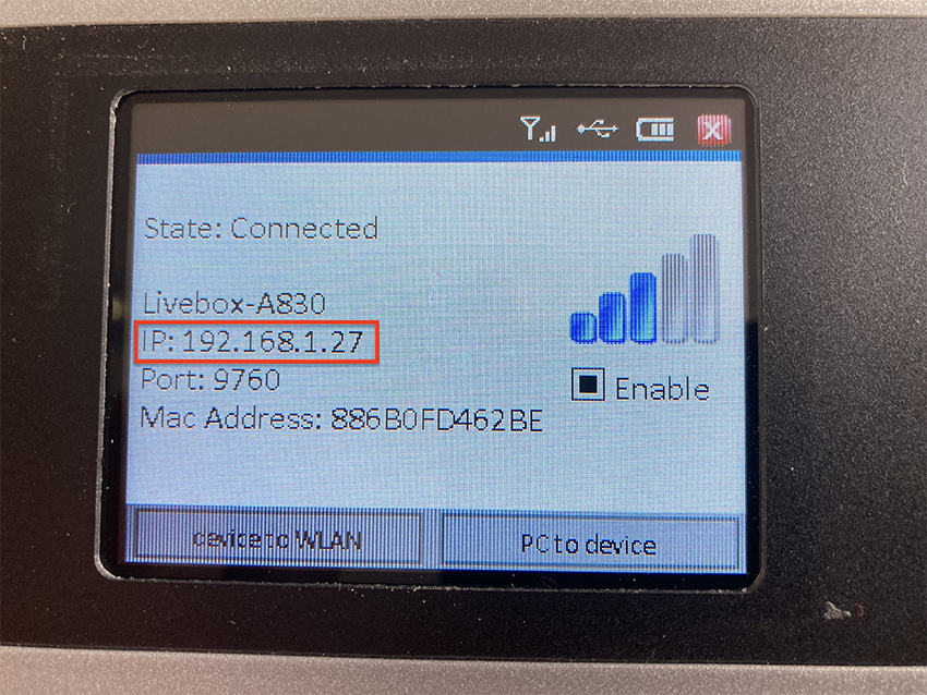
The Wi-Fi parameters are configurable by clicking on the "device to WLAN" button
Report the IP address in Coraye
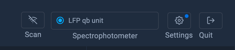
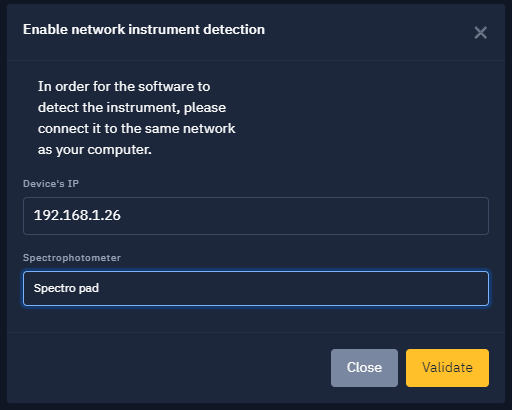
Click on the "Enable network instrument detection" button located at the top right of the Coraye window

In the window that appears, type the IP address of the Barbieri LFP Sensing Unit (Ex: 192.168.1.27) then select the model of the spectrophotometer (In our example: Spectro LFP qb unit). Click on the "Validate" button
Congratulations your Barbieri Sensing Unit is ready to use
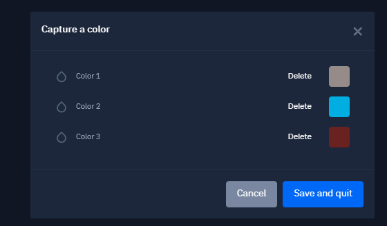
Sample measurement with the "Color Capture" function
For more information, see chapter: Capturing a color
To measure color samples, press the "Measure" button on the touchscreen of the Sensing Unit.

The colors will appear in the Coraye window
The use of the "Color capture" module is detailed in the "Color capture" tutorial:
For more information, see chapter: Capturing a color
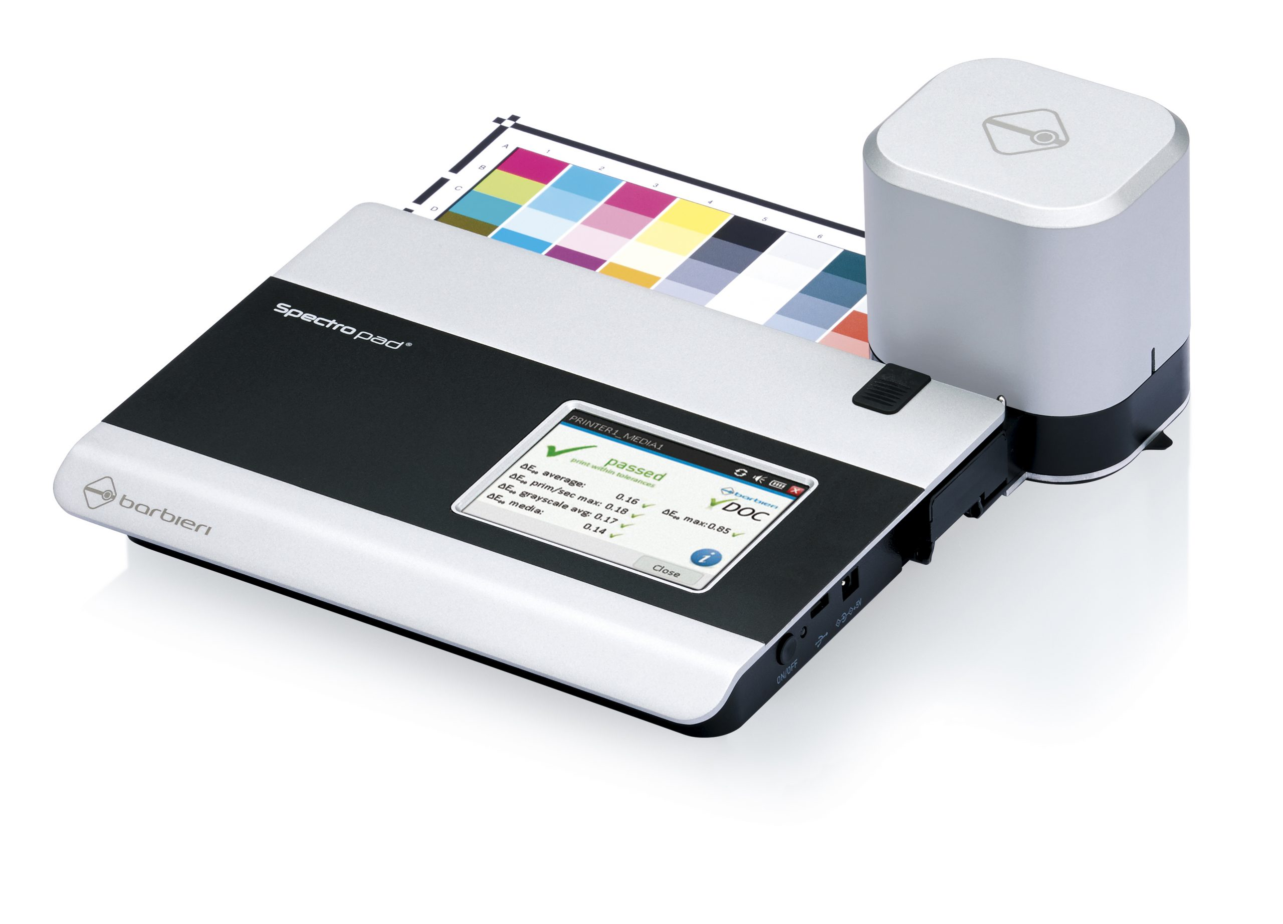
Barbieri Spectropad
The Barbieri Spectropad allows you to measure control ranges and measure ranges for the characterization of printers
Turn on the spectral unit by pressing the button on the back.
The screen will display the following content: The "Calibrate device" button performs an automatic device calibration by automatically inserting the internal reference blank and performing the calibration.
USB connection or Wi-Fi network
Coraye gives you the possibility to connect your Barbieri Spectroscan spectrophotometer via the USB port or via the Wi-Fi network connection.
First of all, make sure that the Barbieri plugin is installed and that the Spectroscan is turned on.
USB connection
When your Barbieri Spectroscan is connected by usb, it will be detected and displayed at the top right in the Coraye window. You won't have to do anything else.

WIFI network connection
If you choose to connect your Barbieri Spectropad to a network via a WIFI connection, it is necessary to indicate its IP address.
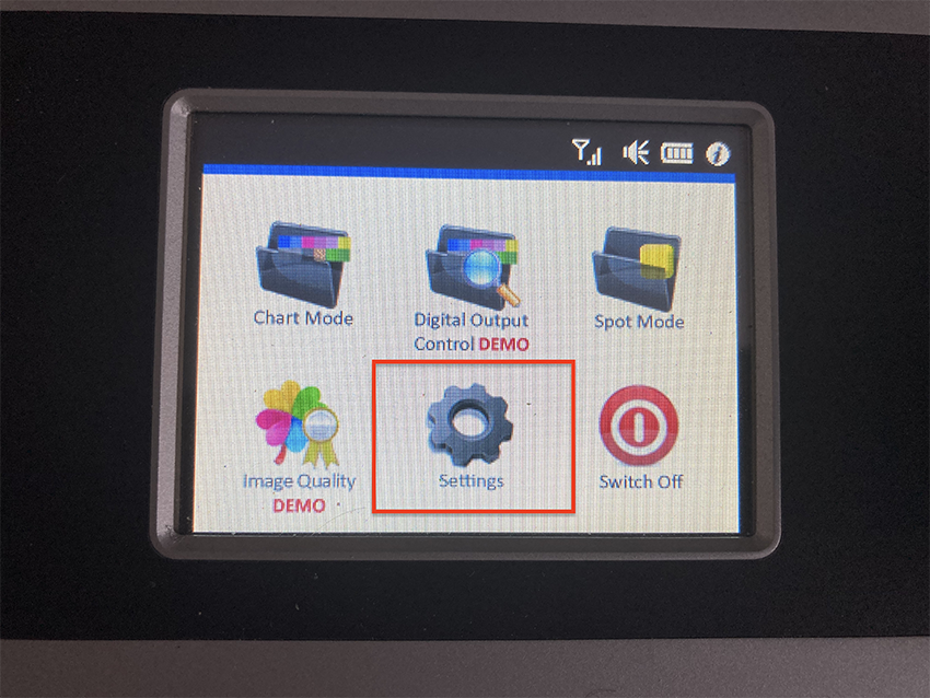
First step: Retrieve the IP address of the Spectropad:
Press the "Settings" cogwheel to access the WI-FI icon.
Select the "Wi-Fi" icon
The IP address appears on the screen
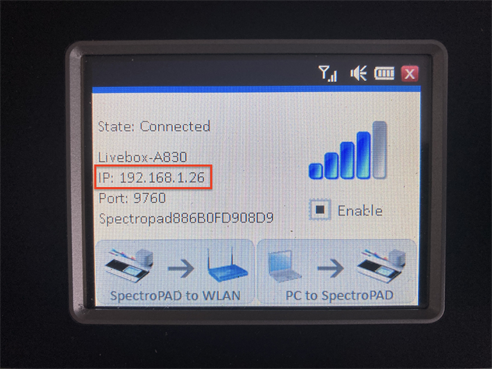
The Wi-Fi parameters are configurable by clicking on the button "SpectroPAD to WLAN"
Second step: transfer the IP address in Coraye
Click on the "Enable network instrument detection" button located at the top right of the Coraye window

In the window that appears, enter the IP address of the Barbieri LFP Sensing Unit (Ex: 192.168.1.27) then select the model of the spectrophotometer (In our example: Spectro LFP qb unit).
Click on the "Validate" button
Congratulations your Barbieri Spectropad is ready to use
Range measurement
To find out more, see the chapter: Creating a profile from a standard test pattern
For more information, refer to the chapter: Printing control
The interface for measuring ranges is the same as for other instruments
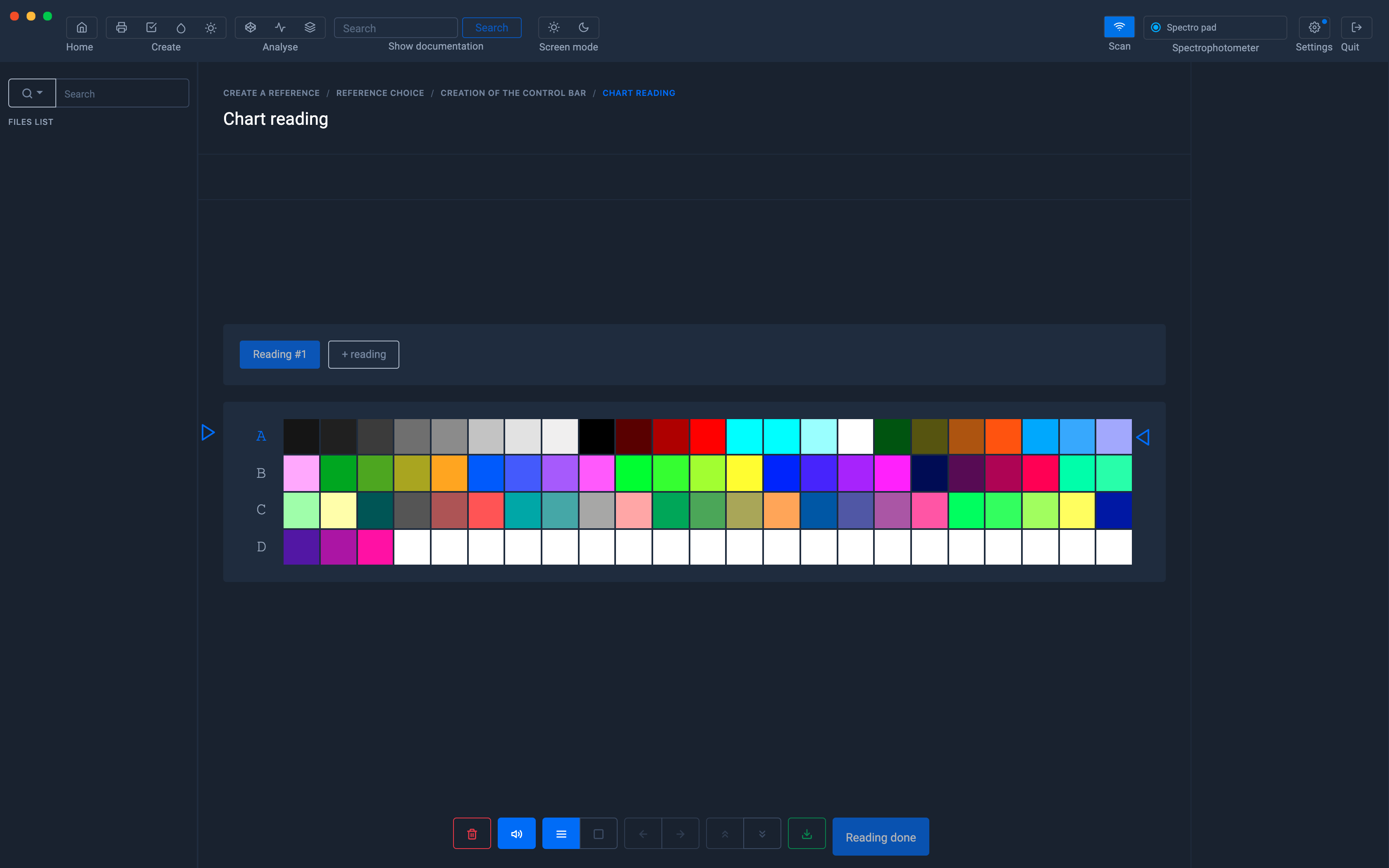
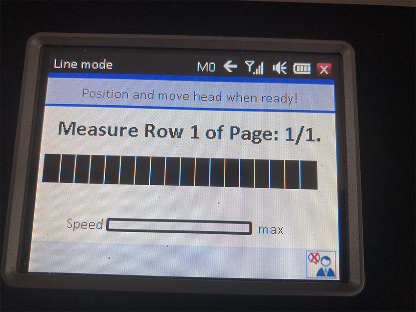
When you start the measurement, the SpectroPad goes into Line Measurement mode.
Follow the measurement instructions
Konica Minolta CM-26 CM-25
Installing the Konica CM-25 & CM-26 driver
The Konica Minolta CM-25/26 driver is only available in Windows version.
Driver download for KM CM-25/26
The drivers are included in the Coraye plugin of the CM-26 which can be downloaded from the dashboard: https://dashboard.coraye.com/plugins
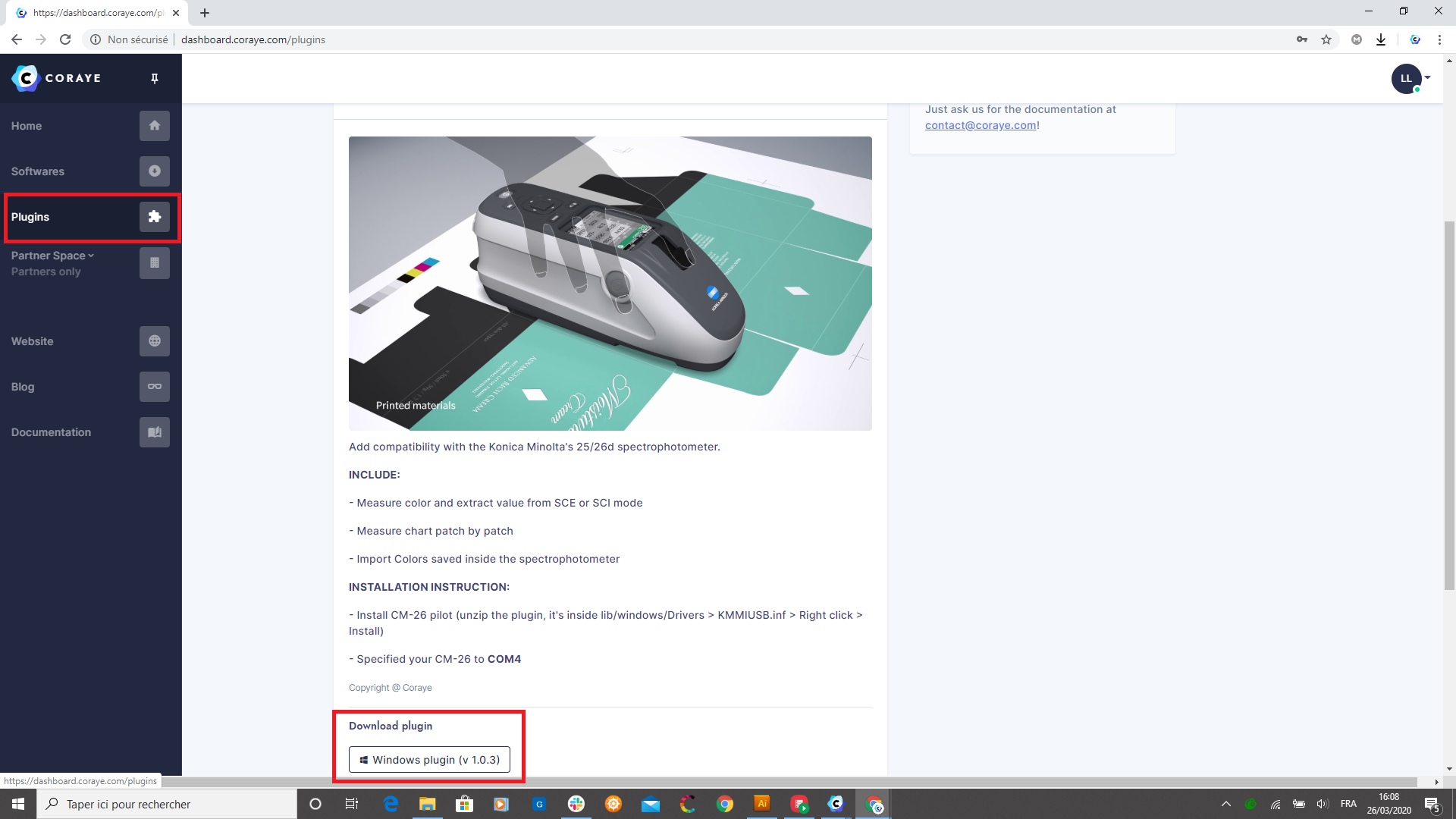
Once the plugin is downloaded, unzip it.
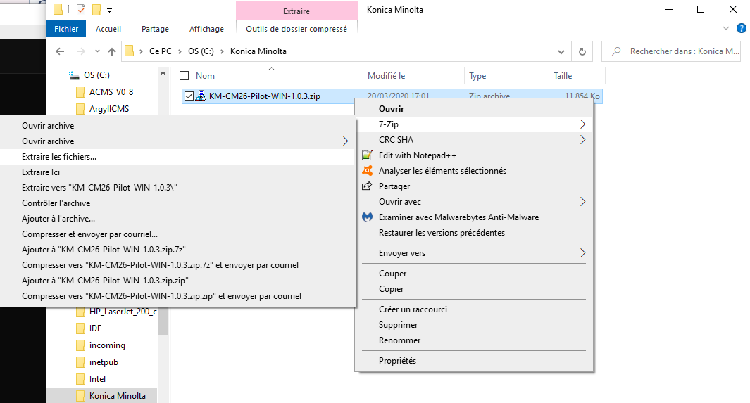
The driver is located in the folder: C: \ .... \ KM-CM26-Pilot-WIN-1.0.3 \ lib \ windows
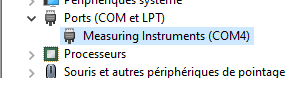
When you connect the KM CM25 / 26 for the first time, it will appear as " USB Serial Device " in Windows Device Manager.
This means that the CM25 / 26 driver has never been installed.
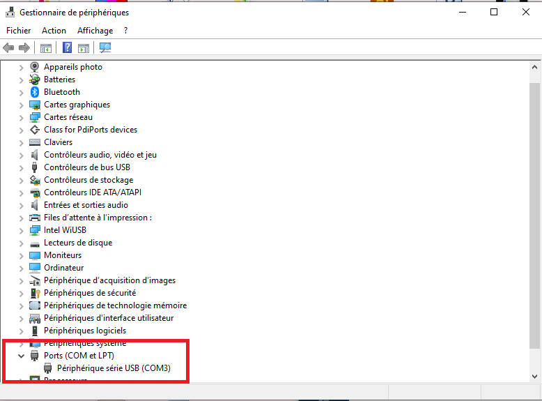
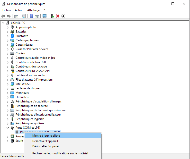
To install the driver, right click on " USB serial device " then select " Update driver "
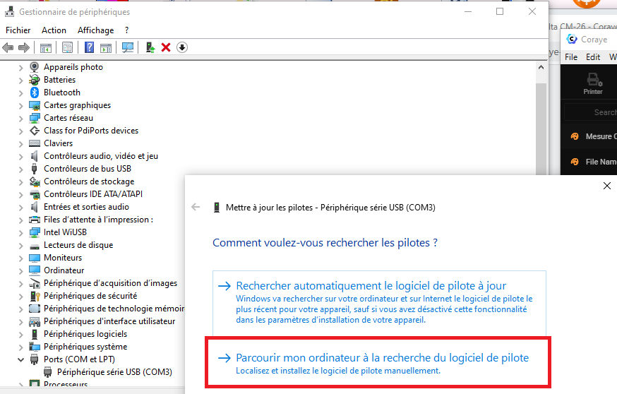
Select " Browse my computer ... " to indicate the path of the folder in which the driver is:
C: \ .... \ KM-CM26-Pilot-WIN-1.0.3 \ lib \ windows \ x64 \
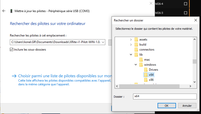
When you have indicated the path, click on " Next "

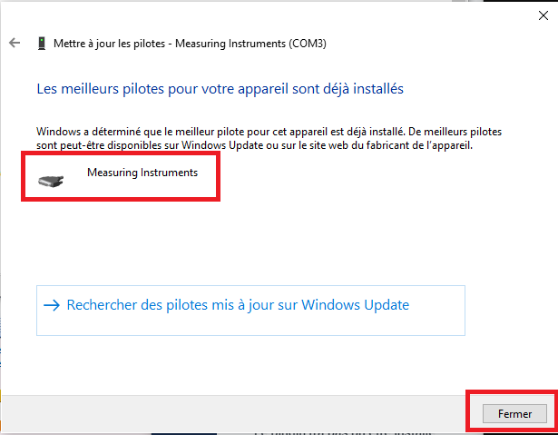
The driver will install, and " USB Serial Device " will become " Measuring Instruments ".
This means that the driver is correctly installed.
Then click on the " Close " button
Modification of the port associated with the KM CM-25/26
To function properly, the serial port associated with the KM CM-25/26 must be COM4.
In the example below, the port assigned by Windows is COM3.
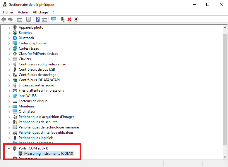
You will have to reassign the COM4 port.
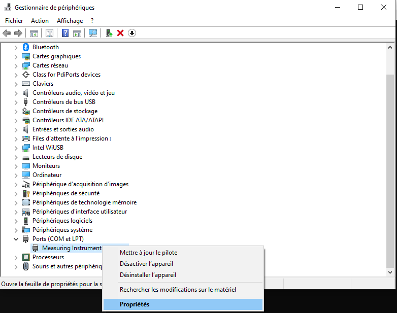
Let's start by right-clicking on " Measuring Instruments ".
Then select " Properties "
Click on the " Advanced " button to access the advanced parameters for the COM3.
Modify the Port number and select COM4 from the list.
Then click on the " OK " button to validate the modification.
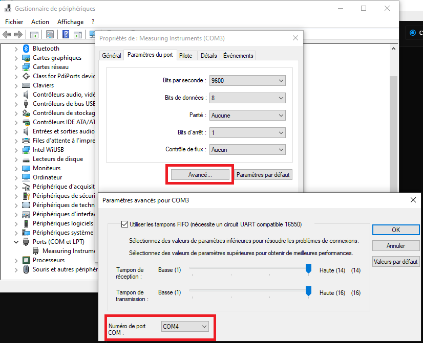
The COM4 port is assigned to the KM CM-25/26
Installation of the KM CM26 Pilot plugin
The installation procedure is described in the procedure: Installing and managing Plugins
To find out more, see the chapter : Installing and managing plugins
Since you have already downloaded the CM-26 plugin in the Dashboard, you can start with chapter 3 of the procedure
Using the KM CM-25/26 with Coraye
With the KM CM-25/26 you have the possibility to perform:
- The measurement of samples with the connected spectrophotometer
- The measurement of samples with the disconnected spectrophotometer
- The measurement of ranges to characterize prints on materials such as glass, metal,
etc ...
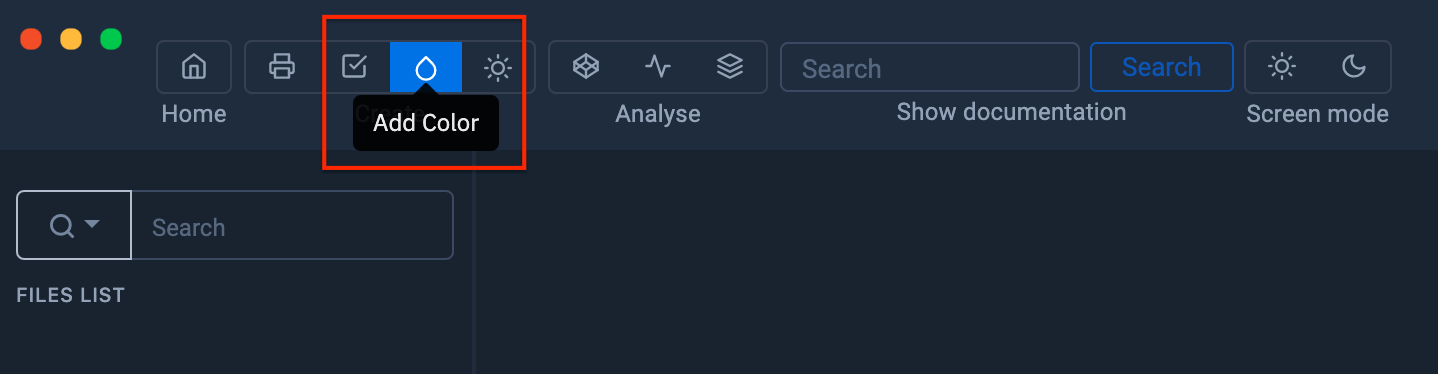
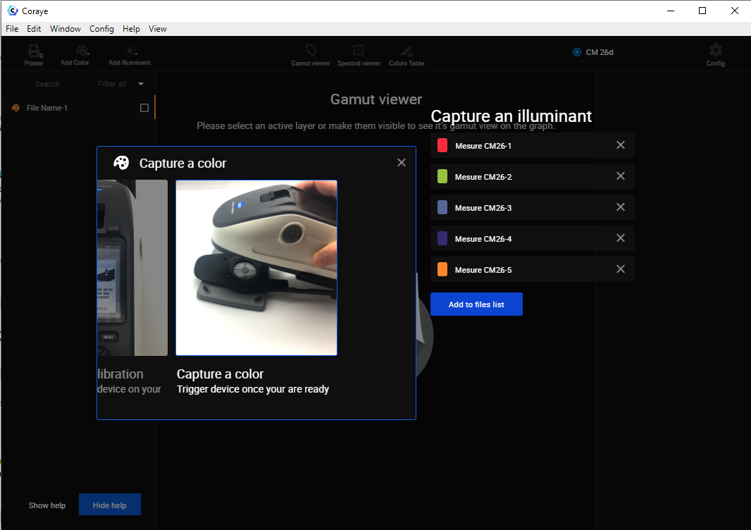
To measure samples with Coraye, launch the color capture module.
For more information, see chapter : Capturing a color
Checking the connection
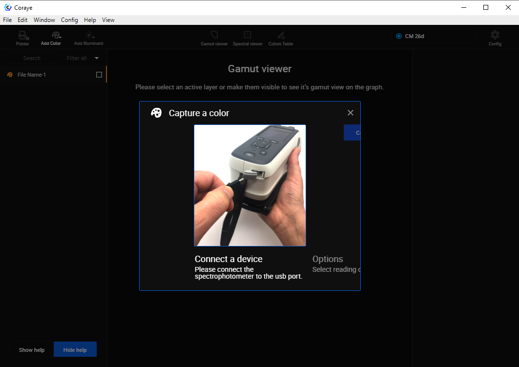
At this step you have the possibility:
- To download the measurements stored in the KM-CM 25/26 or / and
- To use the KM CM-25/26 to capture directly in Coraye, the color samples via a USB connection .
Import of measurements stored in the CM-26
By clicking on the " Import a reading " button, the samples stored in memory will be transferred to Coraye, then the spectrophotometer memory will be erased.
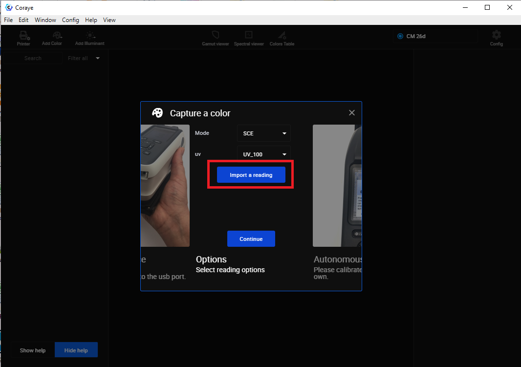
Measurements with the spectrophotometer connected via USB
Before clicking on the " Continue " button, remember to check the measurement mode you want to use (SCI or SCE) and also if you want to take into account the incidence of UVs.
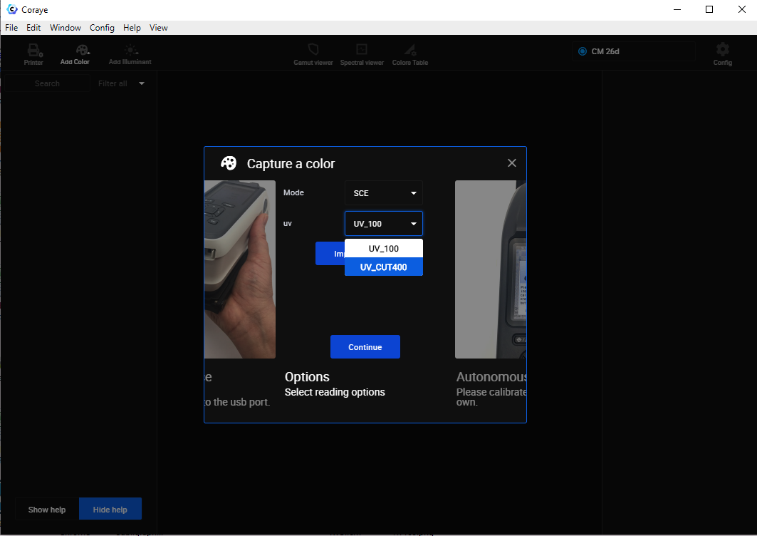
UV mode selection
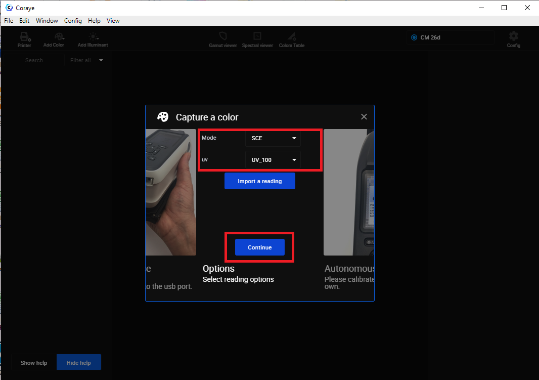
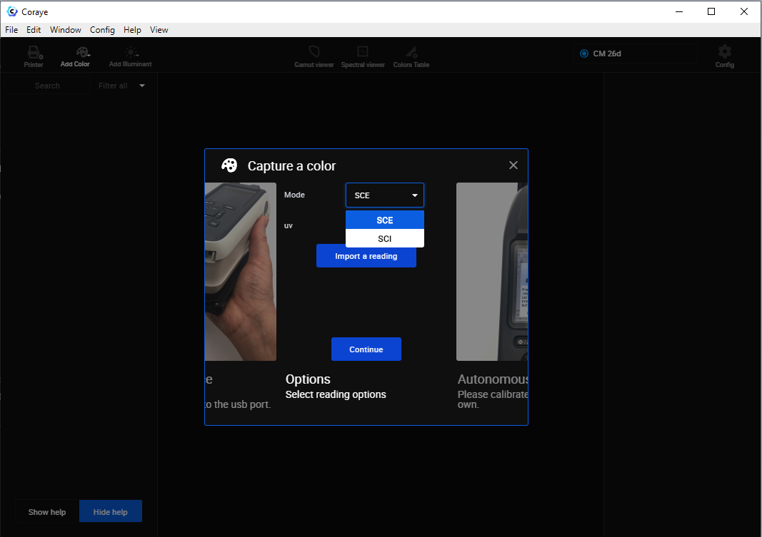
Selecting SCI or SCE mode
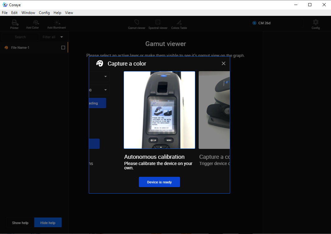
Coraye does not allow you to launch the calibration from its interface.
The calibration is therefore done on the KM CM-25/26 directly.
The procedure for calibrating the KM CM-25/26 is explained in chapter 2 of the manual, section "Calibration".
You will find the links to download these manuals at the end of the chapter.
When you have performed the calibration, click on " Instrument is ready " to proceed to sample measurement.
For the rest, refer to the chapter " Capturing a color "
For more information, see chapter: Capturing a color
Import of measurements taken
Creating an ICC profile with a KM SC-25/26
The method of creating a profile with a KM SC-25/26 is identical to other spectrophotometers.
All you have to do is follow the " Create a profile " procedure.
To find out more, see the chapter: Creating a profile from a standard test pattern
Do not forget to select the right reading modes
The measurement of the range being done patch by patch, it would be a shame to notice at the end of the measurement, that you made a mistake in choosing the SCI / SCE mode or UV100 / UV CUT400 especially after measuring 1000 patches ...
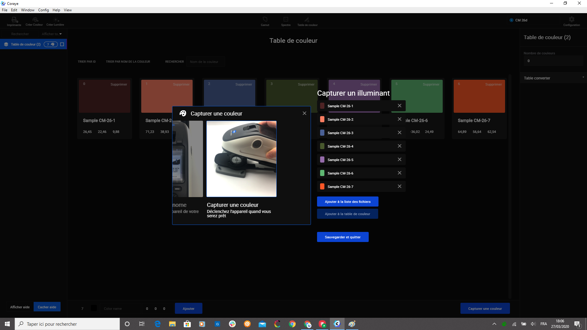
Measuring samples in a "Color Table"
The method for adding samples to a color table is the same as for other spectrophotometers.
For more information, see chapter: Color table
KM-25/26 User Manual
User manuals can be downloaded from the following addresses:
In English: https://www.konicaminolta.com/instruments/download/instruction_manual/color/pdf/cm-26dg_instruction_eng.pdf
In German: https://www.konicaminolta.com/instruments/download/instruction_manual/color/pdf/cm-26dg_instruction_deu.pdf Other languages: https://www.konicaminolta.com/instruments/download/instruction_manual/color/index .html
SCI / SCE mode with or without UV
SCI Mode: Specular Component Included
SCE Mode: Specular Component Excluded
Link to a Konica Minolta blog explaining the difference between SCI and SCE mode: https://sensing.konicaminolta.us/blog/specular-component-included-sci-vs-specular-component- excluded-sce / Mode UV 100: Measurement with UV source to react optical brighteners
CUT400 UV mode: Measurement with filtered UV below 400 nm to ignore optical brighteners
Example of measurement carried out on a glossy Chromaluxe plate
A gray sample was measured with the four reading combinations: The display of the reflectance curves makes it possible to visualize the difference in measurement between the different modes:
- SCI - UV100 (Red)
- SCE - UV100 (Blue)
- SCI - UV CUT400 (Orange)
- SCE - UV CUT400 (Cyan)
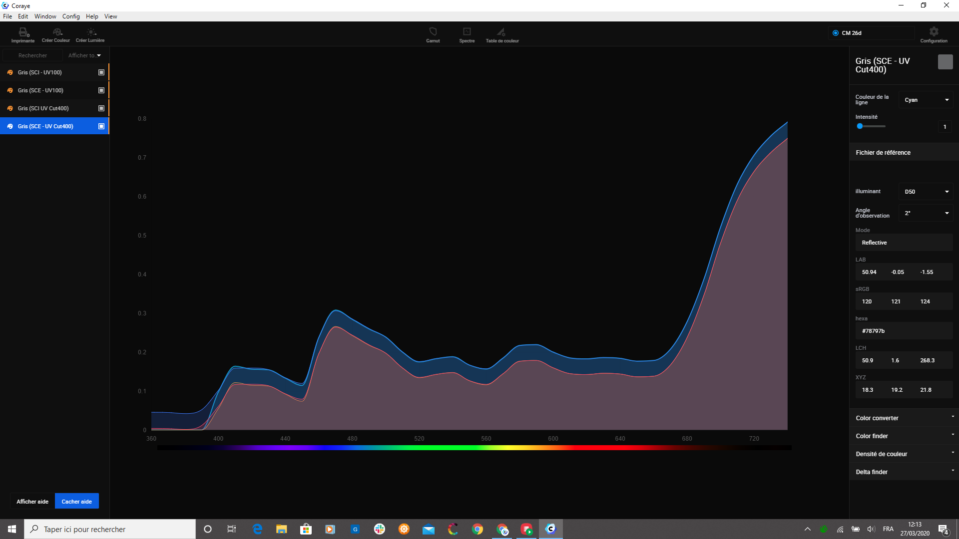
Note: On the right column you can directly obtain the information associated with the selected sample.